12 August 2013

EtekChopper: Using the Sevcon Gen4 Motor Controller

The Sevcon Gen4 is both a truly great and reliable controller and a royal pain of finicky finickage. But it can do this: 


On one hand, it's well built, infinitely customizable, has lots of safety features, and is truly a 21st century controller that's years ahead of Kelly Controls in terms of features. I'm really not worried about dropping it a couple feet, the thing is built solid. It has internal pre-charge monitoring, and when you give it logic power it precharges automatically until it's ready to activate main battery power, and then trips a contactor relay, and then has internal economization for keeping that relay held efficiently. 
Getting down to the nitty-gritty, I can change EVERYTHING. Perceived motor inductance, max stator current, max RPM, PID gains on speed or torque controllers for both drive and regen braking. I can have 10 of them on a CAN network and drive them each individually. I can use a single throttle to drive two separate motors for two-wheel independent torque-vector drive. Or I can put one on my motorcycle and make it go VROOM VROOM (Okay, more like whirrrrrrr). 

But on the other hand, if you mess up any of the hundreds of variables, it will have many faults on it and won't work until they are dealt with. Once they are dealt with, there's still a strong possibility it will just dump current into the motor but not do anything. Or it'll dump current into a different motor lead and spin uncontrollably, threaten to fly off the clamps that are holding it down, at the slightest touch of the throttle, leading me to have to disconnect the main power. Not sure if that's awesome or scary. But I've gotten it right. I got my motor spinning properly and controllably. This is my journey, documented as best I can for reference to the EV community, because many are ready tame the Sevcon, and this may just help them get a handle of it. Because it's supposed to be more a reference to other than to me, I will be rehashing some of the stuff I've written in previous posts into this one. 


Let's begin our journey, then!

First things first is selecting the proper Sevcon Gen4 for you. I didn't have much choice, seeing as I was just gifted the $925.00 Sevcon Gen 4 Size 4, the 80 volt 350 Amp peak version. (I know this because it has a 355 Amp fuse on it, and the manual states the 350A peak version needs it on page 33. And the general brochure states the 350A version is meant ofr a 80 Volt system.)

As for picking a good motor for you controller setup, I guess it's a matter of the max motor current and voltage, and continuous current. My Brushless Etek motor can deal with 300+ Amps peak, 150 Amps continuous, at 5000 RPM (probably a bearing rating, and I can probably push it quite bit harder if necessary). As I recently found out (will detail this in a later post), my special snowflake special edition Etek motor has a Kv of 60 RPM/Volt. Nominally, this means 3.3 Volts per series cell * 24 cells in series * 60 RPM/Volt = 4752 RPM. So it's almost perfect for this controller. 


Now to figure out the wiring. Above is my setup. Note that my motor is clamped down to the table in multiple spaces, so it doesn't go flying across the room from the 50-some NewtonMeters of torque, dragging the controller and batteries with it. 

For a good reference, look at the diagram on page 56 and the table on page 35 of the manual.  The Sevcon Gen4 needs the following to function bare-minimum: 

  • A Brushless Motor of some sort, with its main U, V, and W terminals tied to M1, M2, and M3 on the controller. 
    • Use thick gauge wire for this to prevent melting. I used 2AWG. 
  • A big line contactor with the coil (switch) leads plugged into pins 2 and 3 and the contactor leads between the battery + and the + side of the controller. 
  • A Battery whose voltage range lies within the voltage range of your controller. Tie the battery ground to B- and the battery high voltage to one end of the contactor. 
    • BE CAREFUL! USE GLOVES! ELECTRIC SHOCK WITH VOLTAGES ABOVE 50V CAN EASILY KILL YOU. Even if it's less than 50V, it'll hurt. 
    • I have a 79.2V nominal battery pack on an 80V nominal controller. 
    • Again, use thick wire for these connections. I used 2AWG. 
  • Logic Power Switch at Battery Voltage into pin 1, 6, or 10. 
    • This is the main "On" switch for the controller, and allows internal capacitor precharging to occur.
  • Throttle, with the high side plugged into pin 34, the wiper plugged into pin 22, and the ground tied to battery ground. (I find it very annoying that there are no battery ground lines anywhere in the 35-pin connector)
    • I use a 0-5k potentiometer Magura twist throttle from EV Drives
  • An encoder of some sort. I use Hall Sensors that uses pins 5, 15, 17, 26, and 29. 
  • Enable switches: Foot Switch (FS1), Forward, and Seat Switch are the bare minimum needed to enable drive, and I had them tied to pins 18, 30, and 31. 
    • You can configure these to be at any of the reserved digital switch pins. 
    • They are considered "On" when tied to battery ground. 
  • CAN bus leads for programming, with CAN high tied to pin 13, CAN low tied to pin 24, and pin 2 (CAN Termination) tied to pin 24 if this is only controller in your set, which it is for me.
    • May also need a separate wire to system ground.  
Yeah, that's a lot to deal with, and there's more involved in the setup to get regen braking or other features enabled, but you'll soon see why every bit of it is necessary. 

In order to start connecting things to the 35-pin header, we need the proper individual female connectors and the large 35-pin housing. I ordered these female connectors and this AMPSeal housing from Digikey. Something ended up being incorrect, however, because when I tried to insert the connectors into the AMPSeal housing and then insert the entire housing into the socket on the controller, there was no connection made between the female and male connectors. 


And so I ended up just putting extra electrical insulation on the female connectors and plugging them directly into the controller. I'll deal with how I'll properly isolate these from each other and the elements later. 


After plugging the logic power into the connector and switching 72V into the logic power input, THE LED TURNED ON! LOOKIT! IT'S ALIVE! I tried plugging everything else in (Contactor, hall sensors, throttle. No CAN or enable switches yet) to see if it would trigger the contactor.

Then it blinked 11 times, clearly a fault of some sort. Page 110 of the manual specifies it's an encoder fault, which could result from the encoders not being attached to the controller correctly. 

Now, here's my issue. I don't know which of the bajillion of internal configurable variables are set, and at what values they set to. Odds are, either an incremental optical encoder or a sin/cos encoder (or a combination) is set to be the default for the controller to look for, and those require different pins, hence the thrown fault. 

The only way to see what's going on in the software is to purchase a USB to CAN converter. However, according to this forum thread, and this one, not any old USB to CAN converter for under $90.00 will do. The Sevcon Gen4 requires a specific $300.00 adapter made by IXXAT which has the required proprietary software libraries for the Sevcon to be happy. 

According to this Sevcon program setup document, the amount of configuration power gained by getting this thing is well worth the $300.00, so I called IXXAT directly (They're closeby in New Hampshire) and purchased one, and I got a small academic discount for doing this project through a student club (MITERS). Carla, their sales representative, was a great help and was able to send me one quckly. 


And here it is. Even came with a free pen! 


Okay. One side is a USB plug, the other is a D9 connector, which goes to the controller.


The manual it came with specifies these 3 wires from the male D9 connector. 


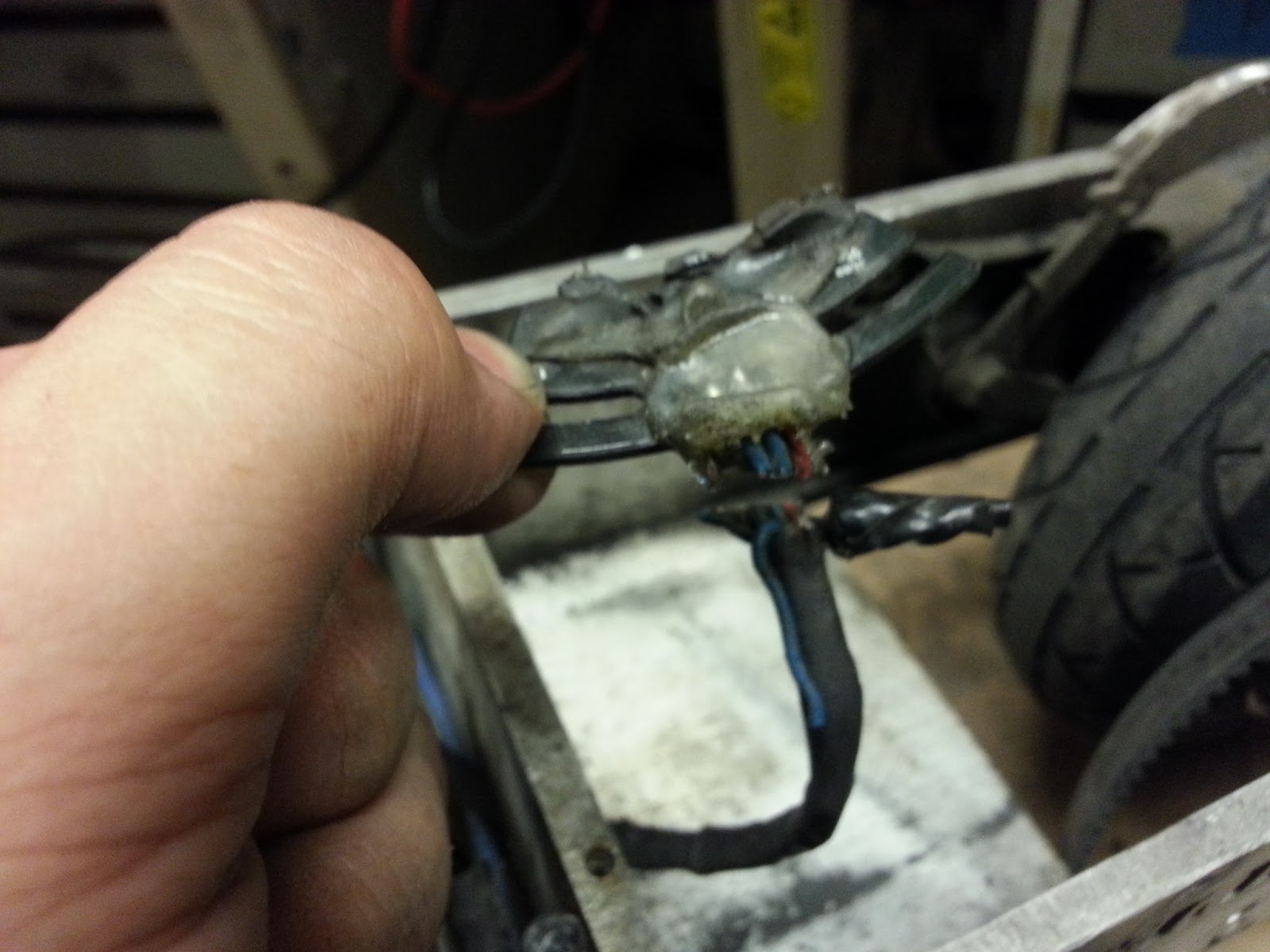
I found a female D9 connector lying around the shop, and soldered 3 leads to it at the appropriate pins. I also soldered a jumper from CAN Low to CAN Termination, necessary for the last device of a CAN bus. 


Here is the default screen of the Sevcon DVT Software. To acquire the software, I called technical support at Sevcon, and a specialist named Joseph was kind enough to send me access to the software, as well as offer some tips for getting the controller working. I would later contact him again to acquire an updated firmware for the controller and a parameter configuration file for the ME0907 motor. 

I later found out you can acquire the software by following the instructions on this forum post, but I believe the software is older and possibly outdated. And after calling up Sevcon they can send you a special download link for free, so there's no reason not to just call them up and get the latest software. 

So, once you got the software running, just follow these DVT instructions. You can see there's an area to change the baud rate for the CAN communication. 


After I set it to the proper baud rate, IT CAME TO LIFE! GREEN LIGHTS!


The controller started speaking, too!


By pressing the "H" Helper button at the top of the screen, I am able to modify controller parameters that pertain to function. The first thing to do is set the controller to Preoperational mode. That will turn off the contactor (if it isn't off already) and enable you to modify the internal settings. I first set up motor parameters based on the ME0907 datasheet, but there were so many parameters that I just left some as they were. 


By looking at the datasheet for the Kilovac EV200 contactor I am able to set the contactor pull and hold voltages. 


I set my throttle ranges using the specified instructions. 


And I am able to test them in the Status tab, and I can see the current perceived throttle voltage as I move the throttle. Cool! 

In addition, I went to the Input/Output tab (Where switch inputs like Forward and the Foot Switch and throttle configurations are determined) and ensured that the first selection was Left Wheel Drive (Joe from Sevcon let me know that is required for drive, in addition to a Forward, FS1, and Seat switch). 


So after doing ALL THAT and going operational, the following faults come up -_-. I played with some settings, and I'm not quite sure what exactly I did, frankly, but I got it to the following uncontrollable state: 

What's happening here is hardcore integrator windup in the controller's torque control system. I can modifythe P and I gains, but I really don't want to mess with them too much because I don't understand the internal transfer function of the controller. I'd rather just call up my friendly neighborhood Sevcon tech support specialist and see what he suggests. 


Joe, the technician who had originally sent me the DVT software was able to send me an updated firmware for the controller as well as a .DCF configuration file for the ME0907 motor. With this config file, I don't have to go about modifying every parameter, but I can load this default one (which includes proper P and I torque control gains) and modify smaller parameters as needed. Remember, while my motor is a little more powerful than the ME0907, it's roughly equivalent, and this will serve as a proper starting point. I'll tweak max current and other settings as needed, as well as later add regenerative braking. 

After flashing the updated firmware and sending the new .DCF file, the following awesomeness ensued: 


Sure, the motor is spinning in the opposite direction it should be, but that's only a matter of playing the sensor game. I have to either shift the sensor leads

And there you have it! In a nutshell, to use the Sevcon Gen 4, you must: 
  1. Have a Sevcon Gen 4, a brushless motor, a contactor, logic wire (18AWG), power wire (2AWG for 350A peak), and a power supply/battery pack
  2. RTFM
  3. Buy the right pin connectors
  4. Buy/rent an IXXAT USB to CAN Compact
  5. RTF other M
  6. Call Sevcon for the DVT software and motor configuration file
  7. Do some finagling, and win!

07 August 2013

Getting the Dyna Myte 1007 CNC Mill Working

TL;DR: 

Here's how it happened:


Towards the end of spring 2013 MIT Prof. Ian Hunter, my lecturer for the class 2.671 (Measurement and Instrumentation Laboratory) and director of the Bio-Instrumentation Laboratory donated to MITERS a 3-axis CNC mill. 

Why, you might ask, would someone donate something as expensive as a car to a humble student shop? Well, it appears five years ago someone replaced the CMOS battery, but in doing so inadvertently reset the computer's BIOS settings. As a result, the software could not detect the machine, and it sat unusable for five years. Instead of getting it working, they bought a HAAS instead, leaving the task of getting the machine back up and running to us. 


It's a Dyna-Myte 1007, manufactured by an old Californian company Dyna Mechntronics. It's named 1007 for having 10" of travel in X and 7" of travel in Y (There are also 10" of travel in Z), so it has a decent build area. 

Other than the 10"x7"x10" build area, this machine sports many other great features like an external flood coolant system and filter, a pneumatic automatic toolchanger with a tool carousel that can house up to 6 tools, an extra servo drive for commanding a fourth rotary axis (Prof. Hunter wanted the original rotary axis, which came from his personal home machine shop, back) and a built-in computer running DOS with decent proprietary Dyna software. 


Now if we can only get it working...


Behold, the computer system of the Ancients! Sporting a whopping 250MHz Pentium CPU, this machine is weaker and takes up more room than a $35 Raspberry Pi. The built-in software running on DOS was not bad, however. It seems capable of doing everything your standard CNC software (like Bridgeport EZTrak, which I am accustomed to) can do with some additional features. 

Upon powering on and loading the Dyna4M software, we were greeted by an instant "Error 465: No Response From Driver." 


Well, let's take a look at the inside of that computer and make sure everything it wired correctly. The interface card between the computer and the large driver board behind the machine is an ISA card, which we later found out takes up the RAM space of COM port 2.


After a couple days of digging through the Dyna 4M software to see if we can expose the internal software configuration, we came upon this. It would appear IRQ 3 is the hardware interrupt resource that the Dyna 4M software looks for to talk to the ISA interface card. Issue is, IRQ3 is currently occupied by Serial Port COM 2. 


To alleviate this, we went into the BIOS and changed all the settings involving IRQ 3. We made sure to disable COM 2's attachment to IRQ 3, as well as any other setting that may occupy the IRQ 3 memory space. 


And it worked! Freeing up IRQ 3 allowed the ISA Card to subscrible the to the proper memory space, and the Dyna 4M software is able to communicate with it! 


YES! We can move axes now! 

However, when we tried to do anything beyond that, particularly involving the pneumatic toolchanger or spindle, the program threw errors. The former was to be expected: we didn't have air hooked up to the toolchanger to allow it to move!


We hooked up an air compressor set to 90PSI to the machine, but it turns out there was a severely leaky solenoid valve preventing the system from working properly. We ordered a new set to alleviate the issue. After replacing the set and hooking up all the hoses to their proper spaces, the fault was cleared!

But led to another one. Great. Now the spindle wasn't working. 

Taking a look in the back of the machine at the spindle driver, it seems there are lots of things that can go wrong. In fact, I count 18 DIP switches, all of which could be incorrectly placed. 

It also seems some of the wires may have come loose from... overzealous rewiring on our part, in an attempt to fix the machine. 


Looking into the back of the machine, I see the spindle driver is a Glentek SMA8115 Brushless servo driver. A quick Google search, and I am browsing the manual for DIP switch settings. Turns out, the default hall sensor configuration for this driver is 120/240 degrees, but the spindle motor has 60/300 degree hall sensors. That got rid of the hall sensor fault, but there was still a drive enable fault. A bit more digging through the manual of the spindle driver and the axis drivers (also by Glentek, but smaller models), and I find that the spindle driver has an active disable (turn a pin to HIGH to deactivate), rather than the axis drivers and their active enable (turn a pin to HIGH to activate). 


As a result, the wiring is EVER so slightly different. Clever girl... see that subtle swap between the green and orange wires? That lets the regular axis interface card output talk to the special snowflake spindle driver. After changing the cable to the proper one, IT WORKS! IT WORKS IT WORKS! NO FAULTS! TIME TO CNC ALL THE THINGS!!!!!!!!

The following will be a set of photos with no dialogue. Just imagine this song playing in the background as you browse through the following images. It's almost like art. 


YAY!

26 July 2013

Cruscooter and MiniJasonTroller or: How I Learned to Stop Worrying and Love Sensorless Control

Cruscooter was my first-ever foray into the world of Personal Electric Vehicles, and one of the best and most reliable engineering projects I've ever worked on. I've been riding it 3 miles almost every day for a year and a half. The reason you don't hear about it much? It works! It works well! The only maintenance has been waterproofing the batteries, occasionally cleaning up the wiring, and replacing the belt/pulley, which I expect to do to any small vehicle seeing daily use. 

The biggest annoyance, however, has been the hall sensors that the brushless Kelly controller uses to commutate the motor, and my bad design choice of making them the lowest-hanging part of the scooter. Many times I have run over a higher-than-normal bump in the road to find my scooter stationary and the hall sensor board ripped clean off. Rain has also affected my hall sensors significantly, possibly altering the magnetic field it needs to keep pushing that motor. I've had to replace them countless times due to running them into things, and they just cut out whenever I run over a puddle. It's always been unexpected, annoying, and time-wasting. 

It rained yesterday. My scooter jerked, sputtered, and stopped, and I told myself "I give up."

I GIVE UP I GIVE UP I GIVE UP! After a year and a half of continuous use, I just CAN NOT anymore. Kelly, you've been valiant and punchy, with your reasonable 40A peak current output and solid 20A continuous current. You've swerved me away from cars and other dangers at intersections when I'm being a an overzealous scooter-er. You've zoomed me past the archaic manual pedal-bikes that seem to control Boston. But your reliance on sensors has wasted my time for the last time. It's time for simplicity, solid performance, and the possibility of blowing up my controller if I start from a standstill.


 It's time for a Jasontroller! A Mini-Jasontroller to be exact. Charles found these on elifebike.com, and put them through their paces in this post. They are sensorless, meaning they estimate the motor position based on current/backEMF sensing. To start from a no-load dead stop, they kinda gun the 3 phases until it starts moving. Once the motor is moving, there is enough information for the controller to deduce the motor position and keep spinning it, with a feedback controller continually adjusting  based on a motor position estimate. 


 As Charles did with a Jasontroller once, I plan on hacking it to put out more power than it was intended to. Charles got a 350W controller to push about 1800W! I don't plan on going that hard, but it shows that more meager overclocking is certainly doable.
That big wire you see above is  ~10 mOhm shunt resistor. The controller measures the voltage across the shunt resistor (usually really tiny, but significant if the current is high enough) and outputs more current until it has reached the desired sense voltage. By lowering the resistance of this shunt, you can make the controller put out more current than it was intended to. Before we have fun with our guinea pig, let's prepare this sucker of hackery. 


 I gave it a haircut. I made sure to check out what wires I was snipping by checking out this page, and ended up snipping everything but the Power leads, Motor Leads, Throttle leads, Throttle on/off switch, and Three Speed leads. 

The Throttle on-off leads I will snip short, solder to eachother, and keep inside the controller housing. The Three Speed Leads have an orange, yellow, and black wire. With none connected, the controller works in medium speed mode. With the yellow connected to ground, it's in low-speed mode. With the orange lead connected to the black wire, it's in high-speed mode. I removed the yellow wire entirely, cut the black and orange wires short, soldered them to each other, and put the whole thing inside the controller. 

And now, the simplest possible brushless motor controller setup in the world! Only three sets of wires to deal with: Battery In, Throttle in, Motor out. 
That's it! It's never been easier to build a personal electric scooter, especially with controllers like these in existence. 

That's not to say this is all better than my previous setup. The Kelly controller is much more sophisticated, and can put out more current and handle higher motor speeds, than the Jasontroller. I'm improving simplicity and reliability in rain, but trading off some speed and some power. 

No more sensors! In one swift and cathartic movement I snipped the wires leading to the hall effect sensor board. It was like breaking one chain (No offense to the perfectly awesome board! It's just an inherent quality of sensored control to be finnicky on the application side). 

When Charles heard I was going sensorless and planned on hacking my Jasontroller, he gave me some of these really nice 10 mOhm resistors which happened to fit right in the gap between the solder leads of the shunt resistor. 

AWW!

I ended up stacking two of them, to lower the resistance to 1/3 of the original shunt resistance (thus making the controller output 30A instead of 10A). 

And here's the test! I threw it in Cruscooter and took it for a whirl, and it was exactly as prescribed: 30A all the time instead of 40A peak/20A continuous, and the top speed is hard-limited in software due to the high commutation frequency. 

But it works! further Improvements include adding another resistor to make it go 40A, switching to a lower-Kv motor (Mine is currently 190RPM/volt. There are Turnigy SK3s that go down to 149RPM/Volt) and/or increasing the size of the pulley from 14 teeth to 16 or 18, thus lowering the gear ratio and increasing my top speed while sacrificing acceleration. 

Keep on scooter-ing! 

22 July 2013

EtekChopper: Electrical Mega-Update

Brace yourselves, this is a Mega-Update!
Last we left off, the mighty brushless Etek/MarsElectric/Motenergy motor had its sensors replaced. It's now time to start putting everything together to start rotating these tires.  

The 35-pin AMPSeal connector required by the Sevcon Gen4 came in, as well as the proper crimp terminals. It's a beefy connector, with rubber gaskets and other protection to ensure the leads do not short and that rain stays at bay.

Looking at the Sevcon wiring diagram in the manual, it dawned on me how complicated this setup was going to be. I need a Main Throttle, a Regenerative Braking Throttle, a Key Switch for logic power, a Contactor to enable supplying motor power, Hall Sensor inputs, an Enable Switch, and CAN Bus inputs for programming the controller with the motor settings and desired configuration. Ultimately, I identified the exact pins I would require: 
  • 1: Key Switch In (Supplies logic power. There are three of these for convenience.)
  • 2: CAN Termination - Short to pin 24 (CAN Bus)
  • 3: Contactor 1 Return
  • 4: Contactor 1 Supply
  • 5: Encoder "U"
  • 6: Key Switch In
  • 10: Key Switch In 
  • 13: CAN High
  • 15: Encoder Return 
  • 17: Encoder "V"
  • 18: Forward "Enable" Switch
  • 22: Main Throttle Wiper In
  • 23: Braking Throttle Wiper In
  • 24: CAN Low
  • 26: Encoder V+
  • 29: Encoder "W"
  • 34: Main Throttle Supply
  • 35: Braking Throttle Supply


I started wiring some of this for an eventual initial test, but first I wanted to check whether the key switch on the motorcycle was sufficient for switching 72V at low current. 

The Key switch in the OFF position does not switch anything, nor does the Lock position, which locks the handlebars of the motorcycle to prevent theft. ON short two of the leads emerging from the switch, and P (Presumably "Park") shorts two others. It seems beefy enough to switch 72V at a low current. Looking further at the bike, I took to figuring out what parts of it to keep or throw away when it came to wiring and indication. 

The original HUD for the bike has a speedometer, engine tachometer, left and right turn signal indicator lights, odometer, brake light, oil pressure light, and high beam indicator light. While somewhat useful, I plan on using the Cycle Analyst (More on that later) as my speedometer and odometer, I can see whether or not the turn signals, brake, or high beam, are activated, and an engine tachometer is not useful if I'm not going to be shifting gears. 

This handlebar-mounted switchbox seems really useful, however. It sports a high-beam light switch (Low beams are always on on a motorcycle by default), Left and Right turn signal switches... 

And a horn button, all in one nifty package. I'm keeping this!

I also received the Cycle Analyst High-Current edition and 0.5-Ohm shunt in the mail. It has a lot of great features, and will serve as my battery voltage indicator, current/power draw indicator, "Gas" (capacity remaining) indicator, Speedometer, and both trip and Universal Odometer. The Cycle Analyst even has more advanced features  to limit current draw or maximum velocity (by putting it between your throttle and motor controller). Because I'm using such a smart motor controller that can already do this, I am foregoing these features. 

The screen is HUGE, and the buttons feel great. It's backlit, waterproof, and runs off of battery voltage. 

It comes with a magnet,which attaches to the bike wheel, and hall sensor which attaches to the front wheel fork. This, coupled with a programmable wheel size, allows the Cycle Analyst to accurately measure velocity and integrate it to act as an odometer. 

The High-Current edition of the Cycle Analyst requires the purchase of a separate shunt resistor for current sensing. This is a 0.5 Ohm shunt, and it's beefy, and can apparently handle 150A continuous (400A peak). 

  The instruction manual is well put-together, featuring informative diagrams and instructions. There's even information on how to hack the device by adding throttle input-output, modifying throttle limit curves, hooking up to a computer for data logging, and even uploading your own firmware. But more on this later, there were more wiring things to test!

Like the lights! While I had the motorcycle inside, I decided to check every light I had. Thanks to one of our favorite awesome battery company's bricks, I verified that the signal lights work, but weren't blinking (yet).

Here's the rear light that's always on. 

And here's the rear light + the brake light in tandem. Sweet. 

Now, because the previous owner of this bike purchased it to remove the exhaust pipes and take the front headlight and turn signals lights. Because of that, he gave the front windshield/headlight/turn signals from another motorcycle. I didn't plan on putting the entire assembly on my bike (It was kinda broken, and I'm not sure it could even mount onto my bike) so I decided to take them all apart and test them. I'll mount them individually with my own adapter hardware if necessary.

It's a shame, it's a really nice front windshield assembly. But hey, onwards. 

I found the part of the motorcycle that makes the turn signals blink! It's a relay-looking thing that probably operates on the same principle as thermally PWM-ing electrical stovetops. Wicked.

I decided to try and start fitting components to the bike while I had it indoors. They... kinda... fit? I'm gonna have to massage the bike a bit to fit those batteries. Chances of me fitting twice the amount of batteries are pretty slim...

 WIRES! I found some of LOLriokart's leftover heavy duty wiring somewhere in MITERS. I need to ensure all my wiring can handle the 350 Amps peak without melting, so 2AWG it is for me! In a hardheaded attempt to get the motor spinning RIGHT NOW, I bought the local True Value Hardware out of all their 2AWG ring terminals. All 6 or so of them. 

 One soldering iron was not enough to properly solder the terminals onto the wire that was about as thick as my thumb. Two irons were also barely enough. So i settled for a propane torch, which ended up working out quite nicely. 

 I dig the result.

 I then acquired the second of the 12S8P A123 packs, and machined an aluminum bus bar to strap between the "+" of one battery and the "-" of another. This left me with ~72 Scary-Ass Volts of A123 goodness. The whole thing was like 30 lbs. I can't even fathom how heavy that would be in Lead Acid packs...

The Tyco Kilovac EV200 is a 12V-activated contactor which can deal with a metric-ass-ton of current. That circuit you see (it's normally hidden beneath a plastic panel) is an Economizer, which ensures low power consumption after the initial contact and current surge. However, according to this post, the Sevcon has built-in economization, and actually cannot work with the Economizer of the EV200. I removed it and soldered the red and black leads directly to the two black leads. 

And here's everything needed to test the rig, almost ready to rock!
It will rock soon, I swear. 
Just hold tight.