Cruscooter was my first-ever foray into the world of Personal Electric Vehicles, and one of the best and most reliable engineering projects I've ever worked on. I've been riding it 3 miles almost every day for a year and a half. The reason you don't hear about it much? It works! It works well! The only maintenance has been waterproofing the batteries, occasionally cleaning up the wiring, and replacing the belt/pulley, which I expect to do to any small vehicle seeing daily use.
The biggest annoyance, however, has been the hall sensors that the brushless Kelly controller uses to commutate the motor, and my bad design choice of making them the lowest-hanging part of the scooter. Many times I have run over a higher-than-normal bump in the road to find my scooter stationary and the hall sensor board ripped clean off. Rain has also affected my hall sensors significantly, possibly altering the magnetic field it needs to keep pushing that motor. I've had to replace them countless times due to running them into things, and they just cut out whenever I run over a puddle. It's always been unexpected, annoying, and time-wasting.
It rained yesterday. My scooter jerked, sputtered, and stopped, and I told myself "I give up."
I GIVE UP I GIVE UP I GIVE UP! After a year and a half of continuous use, I just CAN NOT anymore. Kelly, you've been valiant and punchy, with your reasonable 40A peak current output and solid 20A continuous current. You've swerved me away from cars and other dangers at intersections when I'm being a an overzealous scooter-er. You've zoomed me past the archaic manual pedal-bikes that seem to control Boston. But your reliance on sensors has wasted my time for the last time. It's time for simplicity, solid performance, and the possibility of blowing up my controller if I start from a standstill.
It's time for a Jasontroller! A Mini-Jasontroller to be exact. Charles found these on elifebike.com, and put them through their paces in this post. They are sensorless, meaning they estimate the motor position based on current/backEMF sensing. To start from a no-load dead stop, they kinda gun the 3 phases until it starts moving. Once the motor is moving, there is enough information for the controller to deduce the motor position and keep spinning it, with a feedback controller continually adjusting based on a motor position estimate.
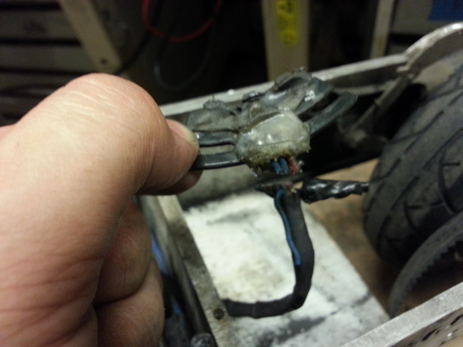
As Charles did with a Jasontroller once, I plan on hacking it to put out more power than it was intended to. Charles got a 350W controller to push about 1800W! I don't plan on going that hard, but it shows that more meager overclocking is certainly doable. That big wire you see above is ~10 mOhm shunt resistor. The controller measures the voltage across the shunt resistor (usually really tiny, but significant if the current is high enough) and outputs more current until it has reached the desired sense voltage. By lowering the resistance of this shunt, you can make the controller put out more current than it was intended to. Before we have fun with our guinea pig, let's prepare this sucker of hackery.
The Throttle on-off leads I will snip short, solder to eachother, and keep inside the controller housing. The Three Speed Leads have an orange, yellow, and black wire. With none connected, the controller works in medium speed mode. With the yellow connected to ground, it's in low-speed mode. With the orange lead connected to the black wire, it's in high-speed mode. I removed the yellow wire entirely, cut the black and orange wires short, soldered them to each other, and put the whole thing inside the controller.
And now, the simplest possible brushless motor controller setup in the world! Only three sets of wires to deal with: Battery In, Throttle in, Motor out. That's it! It's never been easier to build a personal electric scooter, especially with controllers like these in existence. That's not to say this is all better than my previous setup. The Kelly controller is much more sophisticated, and can put out more current and handle higher motor speeds, than the Jasontroller. I'm improving simplicity and reliability in rain, but trading off some speed and some power.
No more sensors! In one swift and cathartic movement I snipped the wires leading to the hall effect sensor board. It was like breaking one chain (No offense to the perfectly awesome board! It's just an inherent quality of sensored control to be finnicky on the application side).
When Charles heard I was going sensorless and planned on hacking my Jasontroller, he gave me some of these really nice 10 mOhm resistors which happened to fit right in the gap between the solder leads of the shunt resistor.
AWW!
I ended up stacking two of them, to lower the resistance to 1/3 of the original shunt resistance (thus making the controller output 30A instead of 10A).
And here's the test! I threw it in Cruscooter and took it for a whirl, and it was exactly as prescribed: 30A all the time instead of 40A peak/20A continuous, and the top speed is hard-limited in software due to the high commutation frequency. But it works! further Improvements include adding another resistor to make it go 40A, switching to a lower-Kv motor (Mine is currently 190RPM/volt. There are Turnigy SK3s that go down to 149RPM/Volt) and/or increasing the size of the pulley from 14 teeth to 16 or 18, thus lowering the gear ratio and increasing my top speed while sacrificing acceleration.
Last we left off, the mighty brushless Etek/MarsElectric/Motenergy motor had its sensors replaced. It's now time to start putting everything together to start rotating these tires.
The 35-pin AMPSeal connector required by the Sevcon Gen4 came in, as well as the proper crimp terminals. It's a beefy connector, with rubber gaskets and other protection to ensure the leads do not short and that rain stays at bay.
Looking at the Sevcon wiring diagram in the manual, it dawned on me how complicated this setup was going to be. I need a Main Throttle, a Regenerative Braking Throttle, a Key Switch for logic power, a Contactor to enable supplying motor power, Hall Sensor inputs, an Enable Switch, and CAN Bus inputs for programming the controller with the motor settings and desired configuration. Ultimately, I identified the exact pins I would require:
1: Key Switch In (Supplies logic power. There are three of these for convenience.)
2: CAN Termination - Short to pin 24 (CAN Bus)
3: Contactor 1 Return
4: Contactor 1 Supply
5: Encoder "U"
6: Key Switch In
10: Key Switch In
13: CAN High
15: Encoder Return
17: Encoder "V"
18: Forward "Enable" Switch
22: Main Throttle Wiper In
23: Braking Throttle Wiper In
24: CAN Low
26: Encoder V+
29: Encoder "W"
34: Main Throttle Supply
35: Braking Throttle Supply
I started wiring some of this for an eventual initial test, but first I wanted to check whether the key switch on the motorcycle was sufficient for switching 72V at low current.
The Key switch in the OFF position does not switch anything, nor does the Lock position, which locks the handlebars of the motorcycle to prevent theft. ON short two of the leads emerging from the switch, and P (Presumably "Park") shorts two others. It seems beefy enough to switch 72V at a low current. Looking further at the bike, I took to figuring out what parts of it to keep or throw away when it came to wiring and indication.
The original HUD for the bike has a speedometer, engine tachometer, left and right turn signal indicator lights, odometer, brake light, oil pressure light, and high beam indicator light. While somewhat useful, I plan on using the Cycle Analyst (More on that later) as my speedometer and odometer, I can see whether or not the turn signals, brake, or high beam, are activated, and an engine tachometer is not useful if I'm not going to be shifting gears.
This handlebar-mounted switchbox seems really useful, however. It sports a high-beam light switch (Low beams are always on on a motorcycle by default), Left and Right turn signal switches...
And a horn button, all in one nifty package. I'm keeping this!
I also received the Cycle Analyst High-Current edition and 0.5-Ohm shunt in the mail. It has a lot of great features, and will serve as my battery voltage indicator, current/power draw indicator, "Gas" (capacity remaining) indicator, Speedometer, and both trip and Universal Odometer. The Cycle Analyst even has more advanced features to limit current draw or maximum velocity (by putting it between your throttle and motor controller). Because I'm using such a smart motor controller that can already do this, I am foregoing these features.
The screen is HUGE, and the buttons feel great. It's backlit, waterproof, and runs off of battery voltage.
It comes with a magnet,which attaches to the bike wheel, and hall sensor which attaches to the front wheel fork. This, coupled with a programmable wheel size, allows the Cycle Analyst to accurately measure velocity and integrate it to act as an odometer.
The High-Current edition of the Cycle Analyst requires the purchase of a separate shunt resistor for current sensing. This is a 0.5 Ohm shunt, and it's beefy, and can apparently handle 150A continuous (400A peak).
The instruction manual is well put-together, featuring informative diagrams and instructions. There's even information on how to hack the device by adding throttle input-output, modifying throttle limit curves, hooking up to a computer for data logging, and even uploading your own firmware. But more on this later, there were more wiring things to test!
Like the lights! While I had the motorcycle inside, I decided to check every light I had. Thanks to one of our favorite awesome battery company's bricks, I verified that the signal lights work, but weren't blinking (yet).
Here's the rear light that's always on.
And here's the rear light + the brake light in tandem. Sweet.
Now, because the previous owner of this bike purchased it to remove the exhaust pipes and take the front headlight and turn signals lights. Because of that, he gave the front windshield/headlight/turn signals from another motorcycle. I didn't plan on putting the entire assembly on my bike (It was kinda broken, and I'm not sure it could even mount onto my bike) so I decided to take them all apart and test them. I'll mount them individually with my own adapter hardware if necessary.
It's a shame, it's a really nice front windshield assembly. But hey, onwards.
I found the part of the motorcycle that makes the turn signals blink! It's a relay-looking thing that probably operates on the same principle as thermally PWM-ing electrical stovetops. Wicked.
I decided to try and start fitting components to the bike while I had it indoors. They... kinda... fit? I'm gonna have to massage the bike a bit to fit those batteries. Chances of me fitting twice the amount of batteries are pretty slim...
WIRES! I found some of LOLriokart's leftover heavy duty wiring somewhere in MITERS. I need to ensure all my wiring can handle the 350 Amps peak without melting, so 2AWG it is for me! In a hardheaded attempt to get the motor spinning RIGHT NOW, I bought the local True Value Hardware out of all their 2AWG ring terminals. All 6 or so of them.
One soldering iron was not enough to properly solder the terminals onto the wire that was about as thick as my thumb. Two irons were also barely enough. So i settled for a propane torch, which ended up working out quite nicely.
I dig the result.
I then acquired the second of the 12S8P A123 packs, and machined an aluminum bus bar to strap between the "+" of one battery and the "-" of another. This left me with ~72 Scary-Ass Volts of A123 goodness. The whole thing was like 30 lbs. I can't even fathom how heavy that would be in Lead Acid packs...
The Tyco Kilovac EV200 is a 12V-activated contactor which can deal with a metric-ass-ton of current. That circuit you see (it's normally hidden beneath a plastic panel) is an Economizer, which ensures low power consumption after the initial contact and current surge. However, according to this post, the Sevcon has built-in economization, and actually cannot work with the Economizer of the EV200. I removed it and soldered the red and black leads directly to the two black leads.
And here's everything needed to test the rig, almost ready to rock!
Meet the brushless Etek/Mars/Motenergy motor (EMMM? EM^3? EM3?). This one has dead hall sensors. How do I know?
Oh. That's how. I also ran 10V to the the red line, tied the black line to GND and scoped the three other colored leads. Nada. I'm going to need those up-and-running if I'm going to be using the sensors-required Sevcon controller.
I decided to call up Motenergy, the current makers of EtekMarsMotenergy Motors, and I have to say their customer service is absolutely top-notch. John Fiorenza, President of Motenergy and I believe one of the original designers of the Briggs and Stratton Etek motor, picked up the phone himself and seemed genuinely interested in my project.
He offered to send me the replacement sensor board free of charge, but while I was in contact with Motenergy I purchased a replacement fan and fan cover for the back of the motor.
It's also on the phone with John where I found out officially my model motor is one of only about 200 manufactured for a special order (someone at MITERS must have picked it up wholesale) and that it is, in fact, more powerful than an ME0907. Sweet.
Now the issue is getting to the sensors. They are deep inside the motor, attached to the inside face of the back plate, past damn powerful magnets, and a shaft well press-fit into a bearing. And that's after you get past the fire-breathing dragon and beachhead, then perform an animal sacrifice. Taking the motor casing apart is like trying to pull apart two ultra-magnetic plates: very difficult.
I got to work making a makeshift mount out of leftover aluminum. My plan is to put the motor in the mill and do...something with it. But I can't just clamp onto the tangential points of the cylindrical motor. The flat edges on this aluminum plate (which is mounted on the dedicated motor mount points anyway) will work perfectly.
Man, I haven't machined anything in a while...
Well, 3 out of the 4 holes ended up lining up. That's what I get for eyeballing it.
I mounted the motor on the mill on top of high parallels to allow the output shaft the room it needed.
Using a length of steel cable, I tied figure-eight loop (not a smart idea with steel cable you want to reuse, but hey it was free and lying around) to one end and snaked the other end under this hole in the motor, over the head of the mill, under the opposite hole in the motor, then back over the mill. After that I pulled the standing end through the loop, tensioned it, and hitched it a couple times for a full hold.
Then it was time to lower the Z axis. I slowly lowered it until...
With a SHUNK, the stator and back half of the motor came free!
I can see why these suckers were giving me trouble: they're HUGE.
I removed the retaining ring from the remaining shaft, but it still would not budge out of the bearing. Time to bring in the big guns...
I began to push it out with a small arbor press when...
The rotating steel bottom of the arbor press flew up and into the motor -_-. It took Nancy and I 10 minutes of prying with a hammer and tapping with screwdrivers before we could get it out.
And so I found parts of Chibikart's old steering assembly and used them as sort of "magnet condoms", due to their aluminum-non-magnetic-ness. After much pushing down with the arbor press, the shaft came out with a CRACK.
Ooh, the inside of the EtekMarsMotenergy Motor! And there's the sensorboard for the taking!
I wasn't expecting it to be all plastic. Then again, I imagine that's to ensure it is weatherproof. Unlike Cruscooter...
Curious, and knowing I would get a new one in a few days, I took it apart. There were the three hall sensors in some kind of SMT package.
Out with the old and in with the new! Here is the new sensor board, fan, and fan cover I ordered.
And it fits like a glove, as expected. Time to repeat the above process in reverse order!
I have to press the shaft and magnet housing back through the back bearing. This time I needed a larger arbor press, so I headed to the FSAE/Solar Car shop.
I re-tied the back plate to the mill and prepared for reassembly.
Before I could reassembly the whole thing, I needed to get the sensor leads back through to the rear end of the motor. This part was tricky, as the hole was teeny and there was a large wound stator in my way. I passed a small piece of twine down through the hole and tied a friction knot to the cable assembly.
I then pulled it up though, eventually needing to remove the rubber gasket to fit the thick cable assembly up.
I then raised the motor up to the rear cover, taking care to ensure they were properly aligned for when the force of the magnet took over.
CRACK!
The magnets grabbed it hard when it was close enough. Right on target.
Time to test the new sensors...
YAY! All three channels worked properly. One last thing to do...