I dremeled out the spaces needed for the fork to fit, and got the fork mounted.

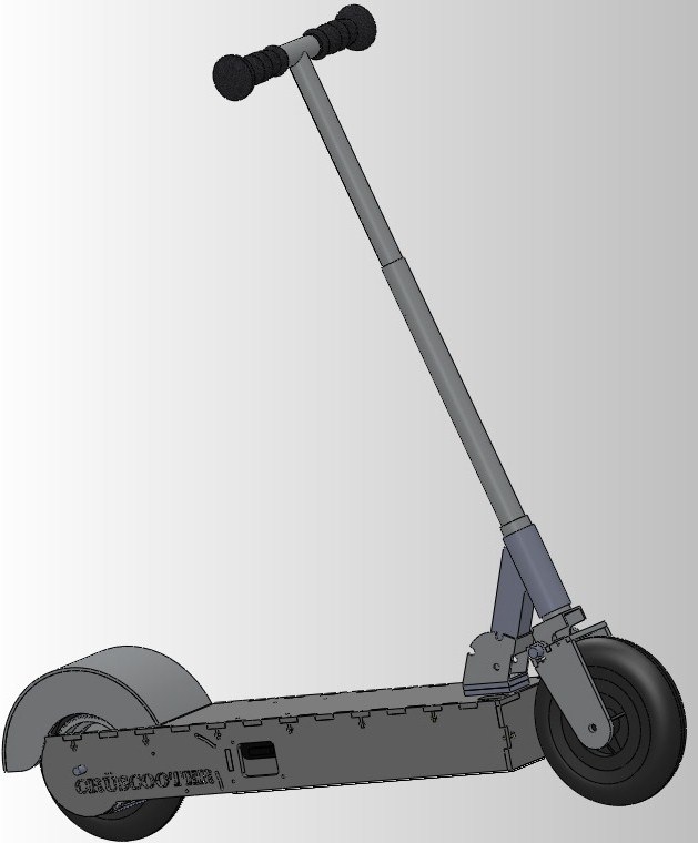
From there, I mounted the handlebar assembly to the rest of the chassis, officially making Crüscooter a rideable kickscooter! Let's ride it around the labspace, ride it around and around, it's wonderful, right?

Wrong. I didn't constrain the front of the top plate because I forgot take into account how it would deflect under load, effectively throwing 2.001 out the window. Oops.

After clamping down the deflected plate for a day, I drilled out a couple holes and tapped them. Two button cap 6-32 screws later, it was effectively fixed.

The brake ended up working better than I expected. Two aluminum standoffs, one on each side, served as hinges for the two sideplates for the fender. A few tapped holes and some bent steel sheet later, and I've got a nice looking fender!

Here you can see the lever (left) that actuates the band brake (right). At the Cambridge Bike Shop, I purchased a brake cable and an old handmedown bike (that had the perpendicular adjustable adapter I needed to mount the cable to the lever) and got the brake working.
Kinda.
After braking, the brake wouldn't reset, meaning the band brake's internal spring force was not enough to return the brake to its previous state. An additional spring pulling the band brake pulley back to its unactuated position solved that problem.

Here's a bottom view of my assembled drivetrain.

WOOHOO!
Now it's time to start entering the realm of the electronics. I made longer handlebars and mounted the throttle. I didn't want the throttle's cable just hanging out, however. I strayed away from the ugly but tried-and-true zipties in favor of snaking the cable inside the Razor's handlebars.

I drilled a hole at the top where the throttle cable can immediately enter the Razor handlebar, and a hole at the bottom where it can come out. The result is elegant and cleaner looking than the zipties that dominate MIT. It also helps that I don't need to rout a brake cable, either.


At this point, I went home for Spring Break for a week, anxious to get back, wire everything in one night
Wiring. And why it sucks when you're sleep deprived.


Look at all them wires. Logic power (doubles as charger port), precharge circuit, motor power, throttle, indicator lights, 3-phase DC motor leads, hall sensor board... yup. All handled by that nifty Kelly Motor Controller.
We interrupt this blog for another episode of What I Learned In 2.007:
When in doubt, just cut the unknown connector off and solder on your own. Don't crimp it, crimps do not hold well.

THIS IS NOT THE WAY A DEAN'S CONNECTOR GOES. THE POSITIVE END IS THE PERPENDICULAR ONE. DON'T PLUG IT IN BACKWARDS.
Kay, got that out of my system.

Here's my hall sensor board, provided to me by my instructor, necessary for our motor controller to be able to drive the brushless motor. I was really tired at this point, having pulled 2 straight allnighters trying to get everything wired up so I could ride the damn already, so I made a really simple mount out of a chunk of plastic available at lab. A couple minutes at a bandsaw later and I had the sensor board mounted.
At this point, I was nearly ready to have my motor driving. After a bit of time of determining which order to plug the motor wires into the contorller in order to get it spinning forward, it was still being really noisy and generally frustrating.
A couple of hours of debugging later and Charles and I determined it was a bad solder connection -_-. ('nother 2.007 lesson: MAKE SURE YOUR SOLDER CONNECTIONS ARE SOLID!).
And... IT'S ALIVE!
Here's some video of me riding up a nearby parking garage.
(Note, it's been alive for over a month now, I'm just bad at updating my blog.)
Yes, the cameraman is chasing me in an insanely fast gokart .
And my fellow EV classmate David, who built this awesome thing with Jacqueline, is sprinting after me on foot.
It has great acceleration, and a decent top speed. I love that I can just hold down the throttle from a standstill and just go, thanks to properly tuned controller settings and the fact that it's a sensored system. It has nice ground clearance, easily going over railroad tracks and small curbs with its 8-inch pneumatic tires. I've also driven it for miles in the rain, and it hasn't skipped a beat yet.
As a vehicle I've been riding every day for about a month and a half, I can say this thing is pretty robust.
I can't pick just one favorite feature. I love how clean the entire thing looks and feels, the way the accelerator wire is routed through the handlebars, the awesome brake mechanism, the sensored acceleration performance from a standstill, the day-to-day range. I built the entire thing in no time at all, so the mechanical design is a cool feature on its own. I'll just go ahead and say it: Crüscooter freaking rocks!
Video from the actual challenge run: a timed drag race and a timed and watt-metered garage hill climb.
I have the green shirt and black hoodie. Yes, Ass-Scooter Mode (c) at 0:40 is incredibly fun.
I think the one feature that really set my scooter's performance a step beyond the performance of most of my classmates' vehicles (I had the fastest scooter drag race time and the fastest AND most energy efficient garage climb of any of the class's vehicles) was the SK3 6364 motor that powered it. It is simply the perfect motor for a mid-sized scooter like mine. My friend Ian used the same motor as I, with similarly impressive results.

And it still fits inside Melonscooter
I've learned a ton this semester. I've gotten deadly with Solidworks and just designing things correctly and precisely. I carry my calipers EVERYWHERE now, and my experience has helped me a ton in 6.141 (Robotics: Science and Systems I, more on that later) for the final challenge, as well as in my general engineering experience.

Thanks in large part to this guy,
I'm an exponentially better engineer for having taking this class, as it's shown me how to apply all the more theoretical principles I've learned so far as a Mechanical Engineer. It's allowed me to flex muscles I never knew I had like CAD design and machining parts. I've had to come up with many different designs, iterate through them to find the best one that fit my criteria. I've had to make compromises and last-minute design changes when things happened.
I've learned a ton, and I really hope this class can continue to touch young aspiring engineers for years to come. I really want to be an Undergrad Assistant for the section next year, if at all possible.
But first...

Yes, this is a thing. And it's freakin' heavy. Let's call it MegaArm for now, and wait til I pass my 2.004 (Control Systems Engineering) final for me to talk about it, shall we?