27 February 2016

2.77 PUPS #4: Kinematic Coupling

PUPS #4: Kinematic Coupling 


Turns out this is a 3D version of my PUPS#2 Planar Coupling. I'm using these projects to test concepts for my final project. 

ADD SPREADSHEET PREDICTION OF PERFORMANCE: 

I haven't used a mill in a while, let alone a fly cutter. It's good to smell like machine oil once again!
There are two pieces of Aluminum stock, one will be the "robot" part, the other the "fuselage". I will make the Fuselage part first, and iterate through concepts for the robot fixturing using the spreadsheet and given the rest of my design work and eventually settle on one. 

I have founded Chip City!

I left the 0.25x0.5" shoulder where the 45-degree taper of the "fuselage stringer" will go.

Chamfer endmill! 

And the finished fuselage section. This was a great exercise in learning the conversational mode on the Makerworks ProtoTrack. 
Here's the real 787 Fuselage for comparison. My Aluminum model is 1:6 scale.

(Aside: The waterjet works again! The pressure sensors on this have been dropping like flies. This one is Serial Number 2, one of the oldest, if not THE oldest Omax still existing.)

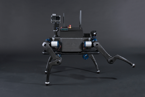
I have a confession to make: I'm using my lab's 3D printer in order to test various concepts. I suppose my project is different in that the entire machine must kinematically couple with respect to the airframe, perform several operations, and then be moved to the next set of holes along the airframe. 


 This ends up fitting quite well! The hole was for a screw to thread through and clamp the Robot down, but its position was arbitrary in this model. This position is currently unstable and pulls the robot away from its coupling location. When the clamping force is in line with at least one of the Kinematic Coupling contacts, ideally more, the clamp will be more stable. 


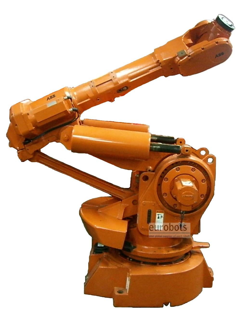
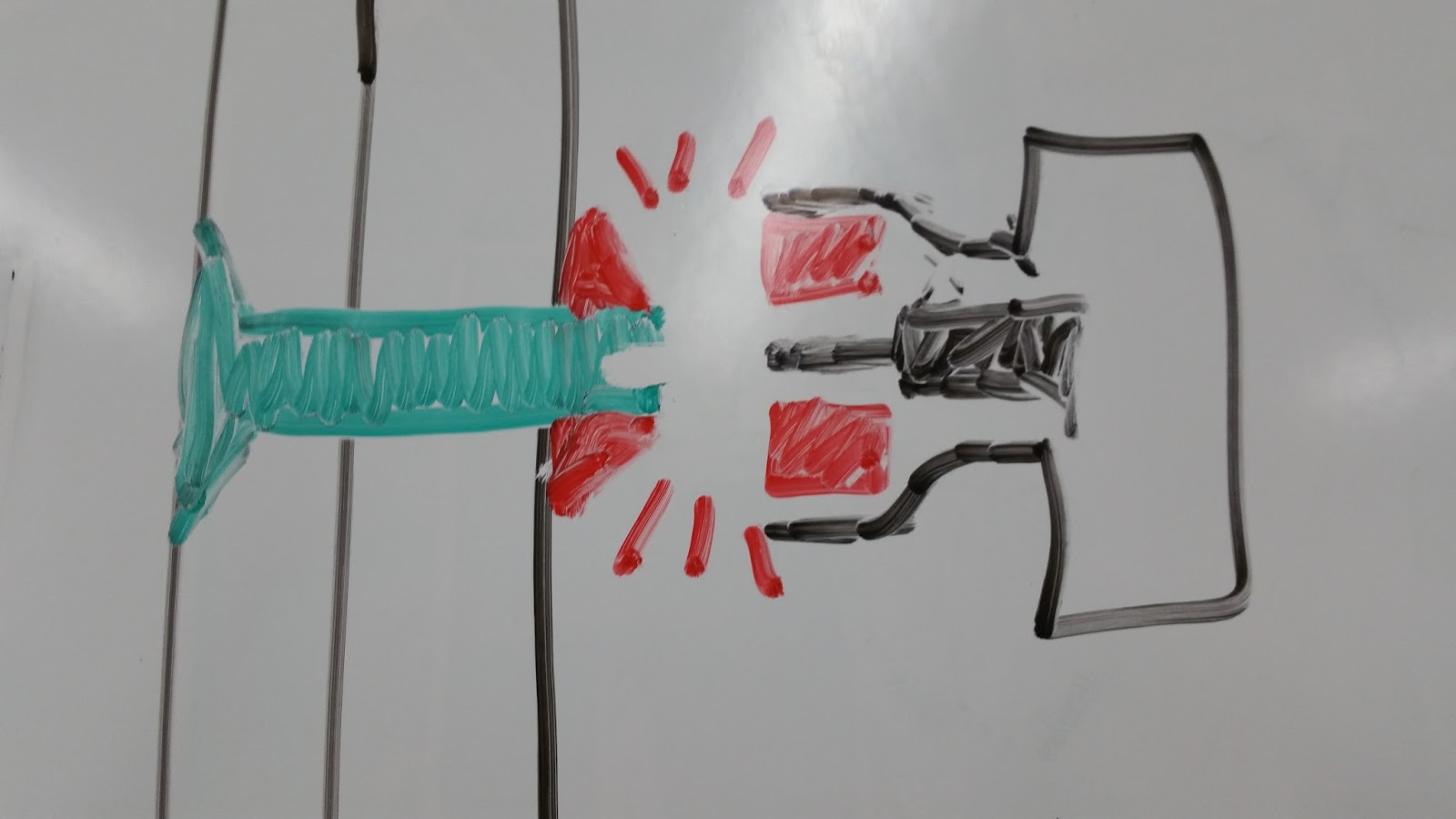
The Big Robot will preload the Fastening Robot by applying both forces and torques against the frame, then the robot will clamp itself to the frame, and the Big Bot will let go. The Fastening Robot can then perform its operation, confident that it is localized with respect to the airframe where it must perform fastening operations. 

TODO WHEN ROBOT DESIGN IS FINALIZED:
Test angular repeatability with a laser in a hallway, Test accuracy with a dial indicator mounted on a mill, Use spreadsheet to modify design and modify if needed. 

2.77 Seek and Geek #4: Robot Leg Analysis/Comparison

Seek and Geek #4: Robot Leg Analysis/Comparison


21 February 2016

2.77 PUPS #3: Machine Design Specification

PUPS #3: Machine Design Specification


 Error Apportionment for Strategy 1: Robot Motion is X-Axis.
This seems like a useful tool to think about how errors accumulate, but the choice of values seems really arbitrary. Here, the structure of the aircraft (which we can't change or control) dominates the error, with the robot moving past the most compliant point between each tack fastener


Error Apportionment for Strategy 2: Stationary Robot with built-in X-axis
In this case, the bearings and general alignment and initial clamping would dominate the error, the robot would be placed and clamped near the tack fastener by the larger "momma" robot for maximum stiffness, and the structure of all 3 axes would all be controllable.


2.77 Seek and Geek #3: Hi-Lok Flush Aircraft Fastener

Seek and Geek #3: Hi-Lok Fastener

My term project for the class involves building a machine whose eventual goal is to install fasteners along the inside of an aircraft (shown above). Thousands of these fasteners connect the big single-piece composite barrel (skin) to the shear ties (latitudinal ribs) that are hoop-shaped L-brackets. 

The holes for each of the thousands of fasteners are drilled, reamed, and countersunk from the outside. The fasteners are then inserted from the OUTSIDE and are perfectly flush with the outside surface of the aircraft, with no features to hold onto. The rest of this job is done on the inside. 
The Hi-Lok fastener has a hex socket on the inside, as well as threads on the outside. By adding a nut and tightening it while using a hex key to hold the fastener in place, the fastener can be tightened completely from only the inside, while the outside, with no mating features whatsoever, remains flush for aerodynamics. 
This is the pneumatic fastening tool used to tighten the bolt onto the fastener from the inside. These are handheld, as most of the fastening is currently done by human workers, though the company has been working on making them friendly to mount on robots with air tool controls. 

One great feature of this system, a way to get precision by design and not by having to torque-control the driver tool, is the frangible collar, or breakaway nut. Once the appropriate fastening torque has been achieved, the nut will separate from the threaded collar to prevent overloading. This is freaking brilliant! When you have a human worker fastening hundreds of these at a time, they get tired or lazy, and it's easy to just beast each one with the air tool until it breaks off when the precise torque has been reached, without needing to actively feel how tight your torque wrench


So, looks kinda like my whiteboard drawing. It seems the remaining collar has no features, meaning it can't be taken out, so it's semi-permanent. I wonder if they use an epoxy as a threadlocker, or if the breakaway nut permanently deforms in such a way that the collar cannot loosen from vibration. Food for thought.