So I ordered almost all the frame materials for Melonchopper off McMaster. Two days and $320.00 later, these arrived at my place.
Inside were all the goodies: 8020 1010 extrusions, .25" and .125" plates for waterjettng the framing materials, aluminum tube for steering column, threaded rods and ball joints for the steering, 30 four-packs of 8020 T-nuts, steering FR-10 bearings, shaft collars, and some additional tidbits. Time to start building!
First, I roughly cut the 6" rear frame cap and steering column support, both made out of 8020. I used a horizontal bandsaw for the first time, only to find out it's terribly inaccurate.
To clean up the crappy job the horizontal bandsaw did, I faced the rough end of the extrusion on a mill.
Already looking good! I temporarily used the steering column support 8020 as a spacer for the front bumper (They're both 6") and placed the seat roughly where it was in the CAD model to determine if my feet would reach the bumper comfortably.
They didn't.
As didn't other tiny aspects of Melonchopper's geometry when it came to seating a person. I'll just modify them as needed, but one thing I'm sticking with til death do we part is the steering. I spent hours tweaking the geometry to make its behavior as ideal as possible.
Speaking of steering, let's cut the shaft down with the bandsaw, shall we?
I also cut the steering rods to the appropriate length with a hacksaw, and cleaned the edges with an abrasive grinding wheel.
And here's one of the nifty 1/4"-28 ball joints. They have two rotational degrees of freedom and allow 70 degrees of play in each direction.
I've done all I can do today. Off to sleep until I can waterjet things...
A few weeks ago, in a search for inspiration for a new mechanical build project, I came upon the following Youtube video:
Needless to say, I was, well, inspired. A Delta Robot is a type of parallel manipulator developed by Raymond Clavel as a professor at his alma mater, the Federal Institute of Technology of Lausanne, Switzerland. It is a design that was engineered to solve a very specific problem: high-speed high-precision pick-and-place manipulation of small, light objects in a manufacturing environment. Circuit Board population comes to mind, as does I Love Lucy.
It is a 3-DOF robot whose end effector can move in XYZ, but cannot rotate in Pitch, Roll, or Yaw. Through clever geometry I have yet to fully comprehend, the end effector is always parallel to the base. There are 3 two-link arms (the bottom link being twin parallel links) which are actuated by three feedback-controlled motors at the top. The top links are constrained by the top actuators but the bottom links are held to the top link and end effector by ball joints.
Before I could build one of these, there are some questions I need answered:
What are the robot kinematic and differential equations? (Find end effector position and speed (X, Y, Z, Vx, Vy, Vz) based on actuator angles: (Theta1, Theta2, Theta3) and their first derivatives). Also Inverse Kinematics (What Theta1, Theta2, and Theta3 are necessary to get the end effector to a desired XYZ?))
What magic engineering makes the end effector always parallel to the base?
Why do most Delta robots I see online have L1 (topmost link) smaller than L2 (the second, bottommost link) ?
What will changing the lengths of L1 and L2 do to limit or enhance my workspace range?
Where should my workspace be? If I am picking and placing, how high above my work plane should I put my robot? If I am 3D Printing?
How should I alter my transmission to be able to bear more load, gain more speed, or gain more accuracy?
What is the greatest load I can bear before the strain (% of deformation) on the links becomes unacceptable? (unacceptable being greater than my design end effector positioning tolerance, which I will now shoot for the stars and make an arbitrary .001" in X Y and Z. Interestingly enough, the layer size (and thus accuracy) of a MakerBot Replicator 2 is .1 mm, equal to ~.004". If I can achieve comparable or greater accuracy than a MakerBot Replicator, I can totally use this as a 3D printer!)
Finally, how can I improve on this design?
Here is a Solidworks assembly I put together in a few hours by looking at a bunch of designs online. This is nowhere near a final product, but it is to help me visualize the robot while I work out the kinematics. In this attempt I made L1 and L2 the same length (L1 = L2) and the size of the Base and Effector exactly the same.
Here are the top joints, whose angles make up the robot's generalized coordinates, thetaOne, thetaTwo and thetaThree. These will eventually probably each be driven by a geared motor with encoder feedback. Like my Pittman 655s.
Both joints for each of link 2's twin links are ball joints, which each have two rotational degrees of freedom.
As you can see in the above photos, the DeltaBot end effector is indeed parallel to the base platform. I've determined this to be due to the fact that the each arm is identical (L1_1 = L1_2 = L1_3, etc) and the bottom links of all L2s are tethered together. But why? Pretty soon I'll start applying all this 2.12 I've been doing and work out the forward and inverse kinematics. Between all this schoolwork. And Melonchopper. According to Shane, the difficulty of solving the Delta robot forward kinematics is more difficult than solving the inverse kinematics, which is completely opposite from your standard serial link manipulator. I'll asplain later. I have a Pset to finish.
Let's abuse the waterjet! Before we go ahead and cut parts for Melonchopper, my buddy Tyler Hamer and I found some nice steel in a scrapbox, and decided it would best be put to use making a couple Batarangs.
Because c'mon, they're Steel Batarangs! :D
After a quick DXF-ing thanks to Tyler, the waterjet is off!
I SEE IT!
Tyler waiting on the jet to finish...
After the Storm
Sweet! Tool Steel Batarangs! Now all we have to do it buff them up, sharpen the edges, and maybe even anneal them with a torch and a dunk in water.
All the crazy makers are doing it. (Seriously, go to Makerfaire and it's pretty hard to distinguish between a 3D Printer peddler and a schizophrenic homeless person). It's all the rage, but I've never needed to use it, nor have I really wanted to (til now). The stuff made from the >$1000 range printers doesn't come out THAT nice, and you need something that expensive to prevent sagging, drooping, and problems and other unwanted stuff. Meh, 3d Printing.
3D printed parts are weak, even if the plastic is ABS. Just take it from Charles Guan's experience of making n front wheel forks (which eventually all broke) for his various electric scooters where n is a decently annoying number.
But still, it's pretty cool stuff, especially because of the efforts of the Makerbot, Reprap and Ultimaker communities, which have paved the way to making 3D printing more inexpensive and readily available to your average Joe. Or Daniel. The parts don't come out too well because the technology is new-ish still, but it's getting there.
I want in on the madness, just a taste, to see what it's all about. Will I find a good use for it? Like making panels to hold switches? Or will I just make myself some figurines?
And where does one go to find things to 3D print?
THINGIVERSE.COM!
Man, this is cool! Yes.
I will be using a MakerBot Replicator available at the IDC (Where we had 2.00Scooter). The software looks just like the Arduino IDE to appeal to the Maker masses, I suppose.
After letting the machine heat up and putting down a fresh layer of painter's tape to prevent the parts from sticking to the printing surface, the machine was off pooping down ABS! Look at it go! Or don't, because it will take hours.
And hours. Until your parts appear! If you look closely, though, there is some kind of mistake on one halfway level of printing.
One of these pieces fell apart as a result :c And I had to krazy glue it back together.
These parts are looking MUCH better. Look at that honeycomb inside! You can pick what percentage of the solid is filled, with 100% being slower but much stronger.
Top view of the pooping...
And they're done!
There's still some residual chipping, but man, these parts came out alright. Really, this machine is impressive.
It's a heart! D'aww! :D I want to make more things. maybe a 3D model of Samus Aran, or some concepts for future projects, or panels for placing switches and stuff. We'll see. Maybe I'll even make my own 3d printer...
Guys guys guys I should start doing things with my infinite motors! I will eventually, at some point, want to detect Quadrature Encoder feedback from multiple motors using an Arduino. Like in MASLAB or for Deltabot or something. So I'm doing it now. Because it's more fun than my homework. http://www.hessmer.org/blog/2011/01/30/quadrature-encoder-too-fast-for-arduino/
Man, this is a great example. Like seriously read this guy's entire blog. It's not terribly long, and it's full of useful stuff. I'm a huge fun of everything he's done.
First thing I need to do to is get the provided code running. Taking a deeper look, it's unfortunately incomplete.
Let me explain:
Microcontrollers, like the AtXmega16a4u running TinyArmTroller, and the AtMega328 that's running in an Arduino Uno, have a feature called interrupts. An interrupt is a function that is called only when a certain event, usually pertaining to the voltage level at a certain pin, occurs. For example, suppose you want to make an LED turn on when a button is held down. You can approach this in two ways:
Method 1 involves a loop that constantly checks whether or not a button is pressed. If the button is pressed, turn the light on. Otherwise, turn it off. This method is simple, and for the application of making a light turn on, is totally acceptable.
However, if your microcontroller supports interrupts, you can create two interrupts. One of them will trigger when the button pin rises, that is, when it changes from low to high (Off to On). When the interrupt triggers, the interrupt handler function turning the LED on is immediately called. The second interrupt will trigger when the button pin undergoes a falling action (ie. The button goes from On to Off). When the interrupt triggers, The handler function turns the LED off.
Now, in the context of a quadrature encoder, you traditionally need four interrupts: one to detect a channel A rising action, and channel A falling action, and a channel B rising and falling action. At each interrupt, you would know what the previous state of Channel A and Channel B were, and could iterate the odometry count appropriately (+1 or -1).
If you want some more reading on how Quadrature Encoders work, and how to use a Quadrature Decoder IC, check this page out: http://www.robotoid.com/appnotes/circuits-quad-encoding.html (The above diagram is grabbed from this page)
Also, let MIT Professor Harry Asada (the lecturer of 2.12: Intro to Robotics and my undergraduate academic adviser) teach you about encoders on page 13 of these free course notes: http://ocw.mit.edu/courses/mechanical-engineering/2-12-introduction-to-robotics-fall-2005/lecture-notes/chapter2.pdf The code provided on Dr. Hessmer's site does not correctly implement a quadrature decoder. In that code, an interrupt triggers only when Channel A rises. He does achieve directionality, one of the primary advantages of using Quadrature encoders, by reading the state of Channel B each time the interrupt triggers, and either adding or subtracting to the count based on that reading.
The issue with using this method is you achieve A QUARTER OF THE POSSIBLE RESOLUTION with a Quadrature encoder. Looking at the above diagram, suppose Channel A is on the outside and Channel B is on the inside. There are 12 black spaces per channel. If you account for both rising and falling of a single channel, you get a resolution of 24 counts per revolution [cpr]. Counting both Channels A and B, your resolution becomes 48 cpr! The code provided in the above example only takes into account when Channel A rises, cutting the resolution back down to 12. I want to correctly implement quadrature decoding, where interrupts trigger in both the A and B channel, and the resolution is four times that of that of just a single channel. Issue is, the Arduino Uno can only have two interrupts enabled at a time. I need four per motor, ideally. Then I thought of some Code Magick: When one of four interrupts is triggered, I could reinitialize each interrupt to whatever two interrupts were possible at a current state!
Then I realized Arduino also could just trigger an interrupt when the state of a pin changed, not necessarily when it was Rising or Falling. That's good, because I can just check both pins at each interrupt, test it against the previous pin reading, and adjust the count accordingly.
(If I wanted to keep only a single interrupt like in the above code, I could modify the interrupt to trigger when Channel A changes, read both channels A and B when this happens, and adjust the odometry count accordingly. This however would still keep me at half the total possible resolution. Using a second interrupt which triggers when Channel B changes is ideal).
Here's my setup: Arduino, Pittman 655 Motor, Computer with Arduino IDE.
Next, I attached the encoder in the correct manner. Looking at the datasheet Tech Support Joe from Pittman scanned me from the 1990s, the lime green wire is ground, the red wire is Channel A, the black wire is +5V power (WTF?!), and the white wire is Channel B. The dark green wire is just shielding for the signal wire.
I connected +5V and GND accordingly, and the Channel A and Channel B cables to pins 2 and 3 on my Arduino Uno. Pins 2 and 3 are the only pins able to trigger interrupts (Interrupt 0 and 1, respectively). Here's the code I used:
/* *Quadrature Decoder */ #include "Arduino.h" #include <digitalWriteFast.h> // library for high performance reads and writes by jrraines // see http://www.arduino.cc/cgi-bin/yabb2/YaBB.pl?num=1267553811/0 // and http://code.google.com/p/digitalwritefast/
// It turns out that the regular digitalRead() calls are too slow and bring the arduino down when // I use them in the interrupt routines while the motor runs at full speed. // Quadrature encoders // Left encoder #define c_LeftEncoderInterruptA 0 #define c_LeftEncoderInterruptB 1 #define c_LeftEncoderPinA 2 #define c_LeftEncoderPinB 3 #define LeftEncoderIsReversed volatile bool _LeftEncoderASet; volatile bool _LeftEncoderBSet; volatile bool _LeftEncoderAPrev; volatile bool _LeftEncoderBPrev; volatile long _LeftEncoderTicks = 0;
void setup() { Serial.begin(9600);
// Quadrature encoders // Left encoder pinMode(c_LeftEncoderPinA, INPUT); // sets pin A as input digitalWrite(c_LeftEncoderPinA, LOW); // turn on pullup resistors pinMode(c_LeftEncoderPinB, INPUT); // sets pin B as input digitalWrite(c_LeftEncoderPinB, LOW); // turn on pullup resistors attachInterrupt(c_LeftEncoderInterruptA, HandleLeftMotorInterruptA, CHANGE); attachInterrupt(c_LeftEncoderInterruptB, HandleLeftMotorInterruptB, CHANGE); }
void loop() { Serial.print("Encoder Ticks: "); Serial.print(_LeftEncoderTicks); Serial.print(" Revolutions: "); Serial.print(_LeftEncoderTicks/4000.0);//4000 Counts Per Revolution Serial.print("\n"); } // Interrupt service routines for the left motor's quadrature encoder void HandleLeftMotorInterruptA(){ _LeftEncoderBSet = digitalReadFast(c_LeftEncoderPinB); _LeftEncoderASet = digitalReadFast(c_LeftEncoderPinA); _LeftEncoderTicks+=ParseEncoder(); _LeftEncoderAPrev = _LeftEncoderASet; _LeftEncoderBPrev = _LeftEncoderBSet; }
Whatever hardware is running the software running this (like my Arduino) should be ideally running at a clock speed an order of magnitude higher than this in order to keep up.
One full rotation. Yup, makes sense.
When I move the motor shaft really fast, though, it picks up a lot of error. I should write a filter to be able to keep up with really fast motor movements.... Not now though. I'm late for class -_-
Ever since the end of 2.007 (2.00Scooter) and the Cruscooter build, I've been looking for an excuse to put the experience I gained in designing an electric vehicle to good use. In 2.007EV, I had the opportunity to test out the motley array of vehicles my peers came up with.
"Splinter Cell", Credit to Tyler Hamer (tyhammer@mit.edu)
Some of my favorite designs were my friend Tyler's wooden reverse trike (fun to drive and incredibly stable, but was severely underpowered and "steered like a battleship"), the melon*-powered Brickscooter my friend Bayley built (a scooter with a custom-built high-power motor controller), and the impressive David Wise/Jacqueline Sly Melonkart. (as the name suggests, it is a gokart driven by a melon motor). Also in the mix were class instructors Shane Colton and Charles Guan's TinyKart and Chibikart, respectively.
*Melon: a Turnigy brand 80mm diameter class brushless outrunner motor from hobbyking.com, capable of outputting about 7kW of power.
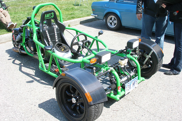
I wanted to combine the designs: make a gokart-style vehicle powered by a melon, with a custom controller, that happened to be a three-wheeler.
Because reverse tricycles are freaking badass!
The Reverse Trike (Probably the incorrect name, usually actually called "Tadpole" configuration) gokart geometry is pretty much just like that of a regular 4-wheeled gokart. The front two wheels steer just like a normal 4-wheeled vehicle, and instead of powering two rear wheels through a differential (Which is a complicated device to make or find), there is a single powered wheel in the center. This offers both simplicity and stability, though you still need to deal with two-wheel steering, which is never trivial.
This is WAY more stable compared to a regular tricycle geometry (Also referred to as Delta geometry), where the rear two wheels are kept facing the same direction (and can be driven through a differential if you'd like) and the front wheel steers. Assuming your configuration contains no leaning (which would mitigate these issues somewhat), if you build up enough forward momentum and want to make a turn, there is the possibility of tipping over the vehicle the opposite direction of the turn.
Here's what I came up with. The six A123 ALMs are there for no reason other than to get an estimate for the storage capabilities. I first put together the basic structure, defining parts to pretty imperial lengths with little though, making this preliminary splatter of ideasauce more art than engineering. The wheelbase is reasonably wide for stability while keeping the 8020 happy.
I used 10" pneumatic tires instead of the trusty 8" ones on my scooter to give me a bit more added traction when maneuvering at high speeds. The tractor seat is one I found randomly on MIT campus for free. The 8020 framing is all held together by waterjet aluminum plates a la Chibikart and Tinykart.
Here you can see the basic steering mechanism and uprights close up. The uprights are pretty much copied from Chibikart's: stacked plates enclosing a steel hex cap bolt (which is the axle). It's a solid design, so I just scaled it up to work with the larger 5/8" shafts required for my 10" wheels.
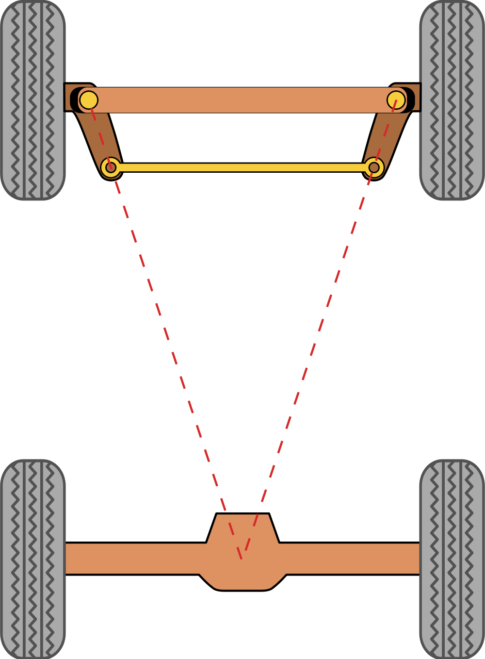
Now I needed to work on the steering geometry. For most cars/gokarts, Ackerman Steering is used to make sure both wheels experience minimal slippage (translating to damping losses and wear on the tires) when turning. To get the whole Ackerman Steering geometry going, I used the following simple diagrams off the Wikipedia page:
See how the front wheels are angled slightly differently?
Thank you Wikipedia for pretty and useful diagrams!
This tells me that when the kart is steering straight forward, the line created by the steering pivot point and the tire rod pivot point should pass through the center point of the rear axle. To get this working with Melonchopper, I temporarilyforced the front wheels to be parallel and face straight. I then computed the required angle needed for the above-described line to work.
Now it was time to really flesh out the steering. Here you can see my initial Designarrhea, before my hours of tuning which actually took into account the fact the the vehicle's operator has legs. I took my "no need to reinvent a perfectly good wheel" approach even further, basing the steering column/tirerod assembly almost directly off of Shane Colton's TinyKart.
However, rather than decouple part of the tire rods to certain axes, which Shane did to allow part of the tire rod to remain completely planar and pass beneath Tinykart's frame, I opted for a single set of tire rods which passed under the driver's legs. The lower and more planar I could place the tire rods, the better, because less nonlinearities show up in the steering configurations. Remember, small angle approximation! (See the link to Chibikart above, where the steering linkages are almost exactly planar.)
Melonchopper, now with More Legit Steering.
With some tuning, I was able to get the steering wheel in a comfortable position while removing much of the nonlinear behavior usually seen in this not-planar nonideal steering configuration.
Driver's view. Pretty sweet looking for my derpy design process, right?!
To test the minimum turning radius (sharpest turn I can perform) and whether or not the steering behavior remained consistent throughout the entirety of the turn, I took the long plates in the uprights and mated them to the kart's structure, where they would hit in real life to limit the steering.
Turns out I can steer pretty sharply while still maintaining the behavior I desire! One issue both Melonkart and Splinter Cell had (to different degrees) was the steering geometry "toggled" to a strange, nonlinear configuration before the uprights hit the physical limits of the geometry (usually the outer wheel was angled more than the inner wheel, which we lovingly dubbed "Anti-Ackerman" steering in 2.007). In my steering configuration (which, admittedly, took HOURS of tuning to get right), the toggled configuration only exists beyond the physical limits of steering imposed by the kart's frame. Therefore, no Anti-Ackerman mode for Melonchopper! The above picture also accurately demonstrates the usefulness of the Ackerman steering geometry: note the left(starboard) wheel is angled a little more than the right wheel.
More POV steering action!
He's going to KILL me for posting this pic :p
Oh yeah, there's a whole other side to this project, the Motor Controller! This enthusiastic fellow is Bayley Wang, fellow MITERS denzien, taker of 2.007EV (He made Brickscooter) and self-proclaimed high voltage expert. Just look at this cute Tesla coil he and some friends designed, meant to be a coil design highschools everywhere can easily use:
Bayley is designing the motor driver with one thing in mind: 7 KiloWatts, which is the full rated power of the Melon motor. Why is this a YAMEB-Certified Big Deal? MITERS has never ever seen the full power of a Melon motor, and this is the perfect excuse to make the 70-volt 100-Amp motor controller we have all been dreaming of. With my mechanical design and his electronic magicking, Bayley and I make an excellent team.
Just to demonstrate how much of a Big Deal this controller is, let's plug it into WolframAlpha with a 15-tooth sprocket on the Melon and the stock 55-tooth sprocket available on the Razor E300 10-inch wheel we're planning on using.
Mother of God...
So, after some highway cruising, we'll stop in New York City for a Broadway Musical, then Of course, we don't actually plan on using this gear ratio. We ended up with something like a 9/110 gear ratio, giving us a ~35MPH top speed and 2MPH minimum speed. And SHITTONS of torque. I'm seriously dreading the day I do my Garage Run.
Oh and we got full ($500.00) Techfair funding for this project. Which is totally enough to get all the parts and stuff. Booyah I can't wait to do some snow drifting this January!


.JPG)