
RAWR! :D
Doesn't this thing look intimidating? Like it wants to hurt you? Muhuhaha!
Here's how it happened:

The rear wheel assembly Bayley found on Ebay for like hella cheap came in! The 55-tooth sprocket pictured here is easily detachable and replaceable. Which is good. Because 100MPH is bad :c

Also here is the band brake it comes with, same design as the one on Cruscooter. It's larger, 90mm Diameter, I believe.

I also found this giant hunk of plastic, Delrin I think. It was someone in the Heat and Mass Transfer Laboratory's final project or something, but it was thrown out next to the lab by all the recycling stuff.
0_0 TAKE!

Using a bandsaw and a mill, I made two of these, each of which is an adapter between my steering column and a steering mount.

Here it is mounted.

Steering's (mostly) done! The wheels steer straight and the steering geometry works out just like it did in the CAD.

I'll fix this problem later. First, the tire rod adapter slippage:

I decided to use my spare face-mount shaft collar to attach to the tire rod adapter that kept slipping whenever I tried to steer, even if it was tightened like hell. I just drilled one .25" hole and fastened them together, which seemed to fix the problem completely.
Only steering problems left are:
1. There's not much leverage with the current steering wheel. You need to apply a lot of force to steer. This can be alleviated by using a larger steering wheel, magnifying the torque you apply to the steering column.
2. The steering wheel is SO F**KING CLOSE TO MY CROTCH. WTF. This can be aleviated by moving the steering wheel as far down as possible (shortening the steering column by a couple inches). This doesn't change the steering geometry at all, and gets the steering wheel away from my precious, but moves the steering column axis even lower, requiring a bigger steering wheel to make it still comfortable. I can also move the seat farther back if I wished, though it would be a pain because of my crappy seat adapter design. I also need to make sure I mount and tension my motor perfectly before I even attempt this.
But all that is for a latter day MITERS session. Now it was time to finally mount the rear wheel! Except...

The shaft diameter of the axle that came with the rear wheel assembly was NOT 5/8", which is the standard for 10" pneumatic wheels -_-. It was actually 10mm, the same size that comes with the 8" pneumatics on Cruscooter.
I could waterjet new plates with holes small enough for the rear axle, which would require time to get waterjet access and bad karma for abusing a waterjet even more.
I could drill 10mm holes into this existing plate, which wouldn't be as pretty or as accurate as waterjetting a new plate.
I could buy new bearings that would fit in this wheel assembly that would take the 5/8" I already purchased. Would take time+money.
I could find parts lying around MITERS and make myself some spacers/bushings that would stay in place during operation. I went with this option, because I love using lathes and I WANT MELONCHOPPER ROLLING RIGHT NAO.

I found myself a rather... interesting looking piece of Aluminum scrap. This was 3/4" diameter, which I could use to make the flange of my

Ahh MegaLathe, my favorite lathe on campus. It's simple. It's robust. It doesn't have a digital readout. It spins beautifully. It can take a freakin' beating. It is in the MIT FSAE/Solar Electric Vehicle Club shop, located a skip and a jump from MITERS. Some groveling and agreeing to clean up more scrap metal than I generated landed me some time on this baby.

And away we go!
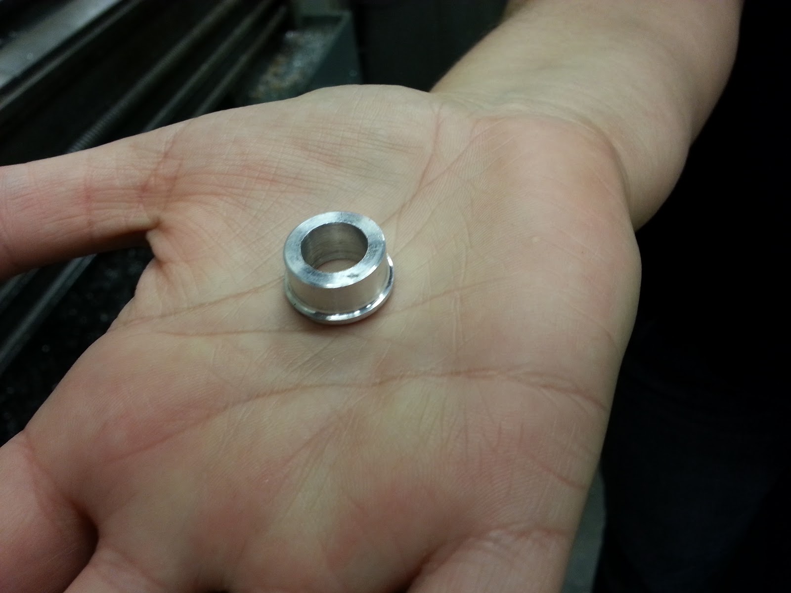
One out of two down. Thanks to my darling friend and the team manager for FSAE Natalie Dostie for providing her hand modelling services :D

And they're both done. D'aww, look at my adorable mechanical drawings! :p

And... they fit!
And I realize i need to tighten the 8020 fasteners BEFORE I mount the wheel. Derp. Another case of Things Dan Didn't Think About When He CAD'ed.

A thing Dan DID think of when he CAD'ed was that the band brake assembly needed somewhere to grab onto, otherwise it would do all kinds of crazy things during operation/braking. And that's just what this lone 8020 fastener does for me.

Now I needed to determine where my rear wheel mount plates should be fastened in order to ensure the rear wheel didn't interfere with...anything. I brought it as far back as I could, to within a quarter-inch of the 8020 butt-piece.

I measured and copied down the distance between the plates part right here, so I could remove the wheel, position both plates and fasten them securely.

Cool, 3/4".

To ensure the two sides lined up, I fastened one end, attached the rear axle to line the sides up, and fastened the other end. Measuring both sides, they were accurately placed.

Now the rear wheel's mounted! :D meaning...

ROLLING FRAME! ROLLING FRAME!

Upon placing my rear end upon the tractor seat for the first time, I realized a fundamental flaw in my design: THIS THING DEFLECTED LIKE HELL.
Like REALLY. I sat down and can get about 45-degrees of torsional deflection by leaning side-to-side. This is because there's no significant cross-bracing between the two main 4-foot 8020 extrusions. Fortunately, the deflection is all in the elastic regime of the aluminum, and it appears there's no significant stress (Force/Area) anywhere along the extrusion. Just an mega-ass-ton(/tons, deflection is a unit-less percentage) of torsional strain, due to all the material that is able to move.
There will be a bunch of material on the bottom for mounting the Battery, Controller, and other hardware, so it may just be an inexpensive slab of... something bolted to the underside.

Makes me wonder, what if I had used welded steel extrusion instead of 8020? I think it would have been cheaper, but it would have also taken me way more time to put this together. I've never welded before. I kinda really want to learn, and make less expensive AND stronger vehicles with the technique.
OH, this brings me to another cool point. This guy. (Follow his blog. FOLLOW IT!) Jeremy is his name. And he's building his own version of Chibikart! And he wants to go to MIT, which, you know, is awesome, because he'll hopefully be another MITERS junkie like moi.
While Charles Guan's Chibikart was optimized for time and ease of manufacturing (as in, you design it, you get the parts, you bolt it together, you ride around. It's more expensive, but faster/easier. MelonChopper takes in this ideology)
Jeremy's Chipikart is a redesign of Chibikart that will end up costing about a third of its predecessor, because it uses cheaper components and manufacturing techniques. Chipikart is optimizing for cost in a very intelligent way, using steel extrusions welded into a frame, milled aluminum bars to replace the stacked wheel upright plates, etc. A truly inspirational build.

And so, MelonChopper rests on her/his/its(?) winch bed for the night. Where it will probably stay until I return from winter break for MIT's Independent Activities Period (IAP).
What adventures will await the DGonz during IAP? Starting work on DeltaBot? A Quadrotor with custom controller softwarez? A Mobile Autonomous System to be played with in a Laboratory? MelonChopperTroller? Custom-laser-engraved stainless steel hip flasks? (I turn 21 December 24)
Yes.
No comments:
Post a Comment