An Open-Source Low-Cost High-Strength Rapid-Prototypeable
Underactuated Robot Gripper
by Daniel J. Gonzalez - dgonz@mit.edu
MIT MechE deFlorez Competition Entry
(Hi, Professor Hover!)
Here is a solid model of my gripper. All of the components can be readily found on McMaster, Trossenrobotics, and other online retailers for under $500.00 total. The parts can be fabricated using only a waterjet, or using online waterjetting services such as bigbluesaw.com. With the solid model released as open-source, just about anyone can put this thing together for use in their robot manipulation project: no expert machining experience required! The design of this gripper is inspired by the WillowGarage Velo Gripper (Work by Matei Ciocarlie):
and the design optimization work of Prof. Aaron Dollar of Yale and Prof. Robert Howe of Harvard:
(link to paper: http://biorobotics.harvard.edu/pubs/2010/journal/Dollar_IJRR2010.pdf). The design of the drive mechanism is underactuated. Specifically, one motor drives both fingers, each of which has 3 DOFs. Passive compliance between each DOF allows the finger to envelop any given object that fits within its grasp without having to perform complicated grasp planning calculations in realtime.
As of this writing, the fabrication process is nearly complete, and it should be 100% functional by the middle of next week (~4/23/2014). An Arduino will receive a grasp command from a host computer (or a button for demonstration) and command the servos to either grasp or let go of an object. The Dynamixel servo is torque-controlled and provides torque feedback, so we can apply the proper amount of pressure for a given object.
Here is an example demonstrating the underactuated closing behavior of the gripper that allows for asymmetric grasps. Using constraint tendons, the gripper acts as a standard parallel gripper until the proximal link encounters resistance. The two distal links then close around the object for a snug grasp.
Here is a cutaway showing the direct-drive spool of the Dynamixel MX64 servo (which can output 7+Nm of torque), the cam lock mechanism actuated by an EMax digital hobby servo, and the main drive cable (Yellow).
Here is a detailed view of the various active and passive tendons and other components within one of the fingers. Each finger is identical.
Thank you for considering my project in the MIT MechE deFlorez Competition!
So I'm about to sit down and write the flight controller for my Quadrotor (My First Quadrotor? MFQ? MFQuad? MFCopter?), but rather than simply document that "I wrote the code and it worked", like I have been doing, I am going to try and be more explicit with my thought processes, in order to become more aware of my coding style, as well as to receive criticism in my style. So, a quad flight controller. What's that? In its most basic form, a Quadrotor Flight Controller (QFC for now, because Three Letter Acronyms (TLAs) are Really Freaking Cool (RFQ)) does the following:
Reads data from the Gyroscope and Accelerometer
Filters it into a usable form
Generate commands the four motors based on the sensor values and user input in order to keep the quadrotor in a certain state, which is usually balancing pitch and roll to keep a stable hovering platform.
Drives motors with these commands
Additionally, a QFC should be able to wirelessly receive commands from an external source in order to be able to move around. This can be as simple as 4 servo commands from a handheld receiver, or as complicated as X,Y,Z,Pitch,Roll,Yaw, and their derivatives. To keep the amount of data being transferred wirelessly down, however, I will keep this down to pitch, roll, yaw, and altitude. Finally, for robustness, the QFC should be able to keep the quadrotor stable in the case of a broken connection mid-flight. Should bytes be dropped or a sudden change in communication occur, an onboard "Lost Connection" timeout will trigger, and the quadrotor will orient itself to a more stable orientation (The Pitch and Roll commands will reset to 0, or a landing sequence will initiate). Okay.
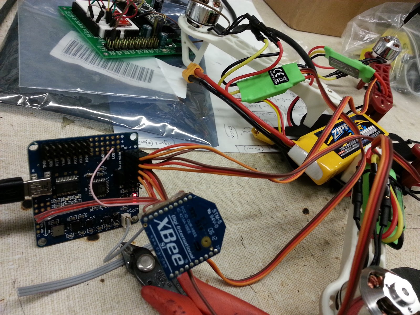
*cracks knuckles* Let's do this. So first of all our QFC needs a way to read sensor data. The gorgeous MultiWii board Shane was kind enough to give me is essentially an Arduino Nano 328 with a built-in 3-axis accelerometer, 3-axis gyroscope, magnetometer, barometer, and a bunch of servo-style breakout pins. The sensors all communicate with the Atmega 328 using the i2c protocol. While I have dealt with i2c communication at my job, every device is different, and requires slightly different requests/commands. Shane gave me some example MultiWii code to be able to start talking with the sensors over i2c.
The above code contains the proper library inclusion (Wire.h) for i2c interfacing, the proper i2c addresses and conversion constants for the various MultiWii board sensors, a function to initialize each of these sensors, the i2c initialization code needed within the Arduino setup() function, and a function to read the raw sensor values from the Accelerometer and Gyroscope and convert them to usable forms (angle, acceleration, angle rate, etc). Note: I eventually want to be able to read the Barometer data, so I found some excellent explanations and example code here (http://www.sparkfun.com/tutorials/253) as well as a more official source of barometric altimetry theory (which i used to great affect in 2.671). For now, we'll ignore the barometer data. In addition to reading sensor data, we are going to need to filter it. The Second Order Complementary Filter that i'm used to requires a PI controller in order for it to work. Additionally, a PID controller will necessary for quadrotor self-balancing, so I opted to write a generic C++ PID class. For more info on PID Feedback Control, just Google it. Wikipedia offers an excellent writeup, as well as an excellent textbook document hosted by Caltech. Here's the generic PID Controller class I've written:
When the class is instantiated, it requires the three PID constants and an option of whether the rate (derivative) is fed to the controller at each update, or if it should estimate it from past timesteps. This last option is useful if you have separate feedback for rate and position (like on this quad, which has both a filtered andle and a dedicated gyro for feedback). Before the controller is used, however, the set point for the control variable must be set via the setDesired() function. The update() function takes the current sensor feedback, as well as the (optional) derivative feedback, and spits out an actuator command. This controller can command the motors of my quadrotor to counteract its roll or pitch angle deviating from the angle I want it at (which is usually 0), maintain a constant altitude with barometer feedback, or act as the backbone for the Second Order Complementary Filter in order to get proper pitch and roll angle feedback by combining both the Accelerometer and Gyroscope data, as I did in 2.12. Here is the entire filter implemented in Arduino:
Sweet! Now in my main loop I can call IMUFilterUpdate() immediately after updating the raw sensor values to get actual pitch and roll, provided I ensure the main loop runs at a frequency of 200 Hz. This can be done with a simple if statement that checks if the time elapsed since the previous run of the loop is greater than or equal to the period (dt = 1/Frequency = 1/(200 Hz) = 5ms). An excellent forum post about the Second Order Complementary Filter (SOCF?) can be found here (post #1286), and a writeup pdf by the author here. Also, is Shane Colton's incredibly useful whitepaper on the First-Order Complementary Filter (Not quite as robust, but super intuitive, easy to understand, and easy to implement).
The Second Order Complementary Filter (block diagram pictured above) works by first integrating the gyroscope data over time ( or multiplying it by 1/s in Laplace space), resulting in an estimated angle. To do that, the the old angle estimate is added to the new change in angle: angleNew = angleOld + (dThetadt * dt); where dThetadt is the change in angle read directly from the gyroscope, in [degrees/s], and dt = 0.005 seconds. However, the gyroscope drifts! Over a short amount of time, the angle estimate will have accumulated error, leading to an incorrect angle estimate (and causing the quadrotor to possibly become unstable). For short-term situations, especially when the helicopter is moving, the gyro is pretty accurate. So this is corrected by taking advantage of the fact that the direction of gravitational acceleration can be found from the 3-axis accelerometer, regardless of the orientation, by taking the arctangent of the horizontal and vertical values of the accelerometer (Or linearizing the angle only using the horizontal component to save computation time, as I did above. The full atan version is commented out). This value is only useful if the quadrotor is not moving, however, and can be waaaay off in situations where the vehicle is accelerating on its own accord. So, we want the integrated gyro data when the vehicle is in motion, and the accelerometer angle estimate when the vehicle is static.
We can use both simultaneously, by providing the angleFilter PI controller the estimated angle as feedback, and the current Accelerometer estimated angle as the set point. The difference will generate a rate command to overcome the gyroscope drift, resulting in a more accurate angle that is robust against both gyro drift AND vehicle accelerations. The values for the proportional and integrator constants, Kp and Ki respectively, can be determined if we model the PI controller as a second order system. The transfer function for the PI controller turns out in a fashion such that
Kp = 2 * wn * zeta;
and
Ki = wn*wn;
where wn is the natural frequency of the system and zeta is the damping ratio. Because we are designing this system (It isn't a physical system with its own uneditable system dynamics), we can set the damping ratio to be a perfect 1 (effectively eliminating the need for a zeta term) and the natural frequency wn to be the frequency at which we trust the gyroscope (or, alternatively, how often we correct the gyroscope with the Accelerometer estimate). I chose a natural frequency of 0.55Hz (period 1.81 seconds), though this may depend on your sensors, loop frequency, etc. I multiply the integral term by dt in order to take into account that our system is in discrete (digital) time. UPDATE on wn: After testing some with this configuration and seeing delay between copter motion and , I've decided to trust the gyroscope even more and make wn 0.045, about an order of magnitude less. The resulting behavior leads to much faster response to copter motion. A good test to see if your natural frequency is correct is to run the code and wait a while and see if the angle estimate drifts. Then, shake (accelerate) your vehicle to try and induce spikes in the angle estimate due to the accelerometer picking up the unwanted noise. If the angle remains stable for both tests, it works! :D
angleFilter.setDesired( AccelerometerEstimate ); angleNew = angleOld + (dThetadt + angleFilter.update(angleOld,0)) * dt; The code all together, which prints out the filtered roll and pitch values of a multiWii328 board:
I began the process by asking the experienced quadrotor-ers around MITERS and the IDC about where to start. Shane suggested I find a 330mm-size frame. Searching the Hobbyking Quadcopter frame section for "330" yielded the following beauty: http://www.hobbyking.com/hobbyking/store/__28172__F330_Glass_Fiber_Mini_Quadcopter_Frame_330mm.html. It seemed big enough to make the controller run smoothly while being small enough to comfortably fly indoors (my flying domain of choice, for now). So I had a frame. To get from here to working quadrotor I need to spec out:
Frame
4 x Brushless Motors
4 x Electronic Speed Controllers (ESCs for short, one per motor)
n x sets of Propellers (Banks Hunter let me know these break often, so I ordered like 5 sets)
Battery Pack
Battery Charger (I did not purchase one because I already have one)
Programmable microcontroller board (Arduino should do)
IMU for angle feedback
Other sensors for other kinds of feedback (usually come with the IMU and ucontroller board)
XBee pair and USB interface, in order to give the quadrotor commands from my computer program.
Looking at the F330 frame's listing on the HobbyKing website gave me the proper specifications I needed for the various components. I chose the components necessary simply based on what was least expensive. I picked the SK3 Aerodrive 2826 motors with a Kv of 1130 rpm/V and many spare sets of red 8", 4.5"pitch propellers (These break often, I hear), which are within the specification range recommended by the F330 frame page. I chose 15-amp ESCs, which is more than I need for this size copter, because they were also well-priced. I then chose the lightest 1800mAh 3s (11.1 V nominal) battery I could find. In order to tie them all together with minimal wiring work, Banks suggested I use a nifty Power Distribution Board to get battery power to the ESCs. As for the XBees, I chose to get this starter kit from Makershed, which was the least expensive option. It comes with a breadboard-able 5V-3.3V logic level shifter (Many electronics run on 5V, the XBees run on 3.3V) and a USB adapter so you can connect to a serial device (like a quadrotor!) wirelessly. I'll worry about the sensors and microcontroller board later, because I have Arduinos and IMU breakout boards readily available nearby. The ESCs each take a 5V servo-style PWM input signal, so an Arduino is be able to command all 4 brushless motors. Apparently the ESCs also generate 5V for the logic power, so no need to use a regular! Total cost? About $150.00. NOT BAD!
Building the Quadrotor:
About a week after placing the order, I received the XBee starter kit from Makershed and the four SK3 2826 motors from the HobbyKing USA Warehouse in the mail. HobbyKing has both an International and USA warehouse, and you can isolate the online selection available from each right on the website. The International warehouse has a wider selection of products, but shipping to the USA is costly and takes forever. On the other hand, the USA HobbyKing warehouse does not have as wide a selection, but shipping to US destinations is both cheaper and more timely. For this build, I ordered everything but the motors from the International warehouse.
After waiting a few more weeks, a package from China came!
And check out all the new toys! From left to right, I see two frames (I gave the extra one to Shane Colton), the ESCs, battery (above), and a shitton of props.
Somewhere in the pile of new toys was the Power Distribution Board that Banks highly recommended I purchase. As you can see, it makes hooking everything together really easy. Kinda looks like a floating nervous/circulatory system quadcopter without a backbone...
Speaking of the backbone, let's put the sexy F330 frame together! The kit came with an instruct- I mean INSTRUCITON MANUAL! It was pretty well-written, though the kit was simple enough to figure out myself.
The flip side of the sheet had the same thing, but written in Chinese and probably with better and more detailed instruct- I mean INSTRUCITONS.
What really bugs me about the kit is there is only enough hardware (screws, etc) to put the thing together, and no extras should you lose any. Metric hardware isn't as easy to come by for me, so this may prove itself to be a pain.
The frame consisted of four identical fiberglass arms placed in an equilateral X formation sandwiched by two carbon fiber plates. Lacking the room to hold the battery and control board (which will presumably occupy the very top) and attach the Power Distribution Board (PDB?), I decided to fasten the PDB to the underside of the vehicle. Sure, live power lines are just exposed for now, but I'll insulate the whole thing before trying to fly it.
The tiny (D'AWW SO CUTE!) SK3 2826 motors each come with the proper mounting hardware (Again, no extras in case the tiny M3 screw wanders before it is secure...). I decided to leave off the top carbon fiber plate for now until I could figure out my microcontroller situation.
The ESCs and extra wire folded up pretty nicely on each arm of the copter. I used small black zipties to keep everything down and prevent general self-destruction from the propellers from chopping things up. The ESCs are sensorless, relying instead on current sensing to commute the motors. For now, I plugged the 3-phase SK3 2826 motors into the ESCs in a random configuration. I will later need to shuffle the leads in order to ensure that each propeller is spinning in the proper direction, producing downward thrust.
The propellers are not all identical. Each set of propellers comes with two pairs (4 total): one pair of clockwise and one pair of counterclockwise props. They are installed diagonally opposite each other on the quad, which is shown in the frame kit instructions. The SK3 2826 motors come with all the mounting hardware necessary to hold the props down. Yet again, no extra metric hardware included should you lose anything. I'm surprised the prop and motor are rotationally coupled by only by the friction force produced by the preloaded washer. I sure hope it doesn't go flying at my face. Or into my arm, for that matter...
Now, for the controller I was going to use an Arduino of some kind, an XBee attached to it, and a spare Sparkfun MPU6050 breakout board I picked up. Shane gave me something that was pretty much all of the above combined! The MultiWii 328P is a board that houses an atmega328 microcontroller (the same that is found on many an Arduino), an FTDI chip for USB-to-Serial communication and programming, and an array of sensors like an IMU, magnetometer, and barometer for stability and navigation feedback. When Shane used it, he wanted to communicate with a receiver via XBee, so he broke out the necessary UART pins on the MultiWii328P to connect to the XBee. He gave me this great looking all-in-one board in exchange for giving him one of the F330 quad frames (Apparently these are never in stock, and I was lucky to be able to find one).
The ESC leads all plugged into the servo out pins of the MultiWii328P board. It's almost like they designed it to be easy to put together! After fastening the board onto the top carbon fiber plate and attaching the plate to the frame, I had a quadrotor!
And there you have it! This was really freaking easy to choose parts for and put together. Next up: Write the software and get it flying!
We're all making New Year's resolutions. I have a few personal ones of my own, but they have nothing to do with this blog. This being Yet Another Mechanical Engineering Blog, I will focus on my engi-nerd-hack-robot-ing goals for this year, or at least the coming IAP (January semester) and Spring semester.
It's a dirty hot mess. Needs major rewiring. And a working brake.
1. Build a semi-autonomous Quadrotor
WAY more details about this coming soon. This will be one of my first projects of IAP.
2. Build a Bi-copter/Tiltrotor. A la V22 Osprey.
Something I've been wanting to do since I saw the attack choppers in James Cameron's Avatar. And something I tried to do last year when I knew nothing. Now I know a little something, and building a quadrotor will help give me an intuition for flying things.
It's a ballsy goal. But hey, I'm a freakin' engineering diva.
4. Finish MelonChopper
Cannot wait til I can drift this thing in the snow :p
5. Learn to weld steel.
So I can build Certified Legit vehicles. For cheap.
6. DeltaBot.
I'm going to have the coolest thesis ever ^_^.
7. Write an Instructable on manipulator robotics.
I've learned a lot in the past few years, time to spread the love. But first...
8. Design and build a ~7-DOF robotic manipulator. A la KUKA arm.
I've been controlling these bad boys, now it's time to be a Mechanical engineer for once.
9. Pay attention to TurtleBot.
Of my children, I've been giving a lot of attention to TinyArm and none to TurtleBot, and I don't think TurtleBot can handle neglect much longer :c. Time to turn that around. I owe Shane a SLAM map of the IDC before he goes off into the Real World (c).
10. Get TurtleBot+TinyArm playing together.
I still hold myself to the dynamic duo, TurtleBot and TinyArm, getting me a soda. Maybe now that TinyArm has learned how to talk, and with the release of ROS Groovy Galapagos I'll finally make it happen.
13. Get a summer internship. I cannot spend another summer at MIT UROPing. I need to see the world. See what industry is like. I need experience. I need to make a difference. I'll probably apply in the next few days...
I've been home for winter break, weary from the end of my fifth semester at MIT (I managed to maintain a 4.5 GPA!), and staying up in the odd hours of the night and relaxing... by working on TinyArm.
Before I went home for winter break, I decided to drop by MITERS to pick up TinyArm, among other things. I hadn't really worked on it since the beginning of the school year, where the last breakthrough was getting it to move around using hard-coded step waypoints in the firmware. I tried for many, many nights to get "zee USB" working... to no avail. Now that I was home, I decided to do a few things. I wanted to model TinyArm, to figure out its dimensions and true limits before I started working out the kinematics/inverse kinematics. I also wanted the model because I wanted to test out the Solidworks-To-URDF Exporter (Now that I had a 64-bit computer). I also wanted to finally get my computer talking to the control board, even if it meant not using the USB protocol directly.
I first grabbed my trusty calipers and began modelling the manipulator in Solidworks from scratch. Luckily, every single dimension on the thing is a proper Imperial value. Some lengths were 8.0 inches, some were 2.5, some were 6.375, but they all had some very nice number. Here you can see the final model I made.
And here's a closeup. The most important dimensions are there, though I may eventually add the cables, gearing, and motors. The gripper even closes the way it's supposed to! Too bad the URDF exporter never worked. Even with only the base links and the shoulder link selected, it was not able to identify the points or axes for each joint. Oh well, I may just make myself a custom URDF anyway.
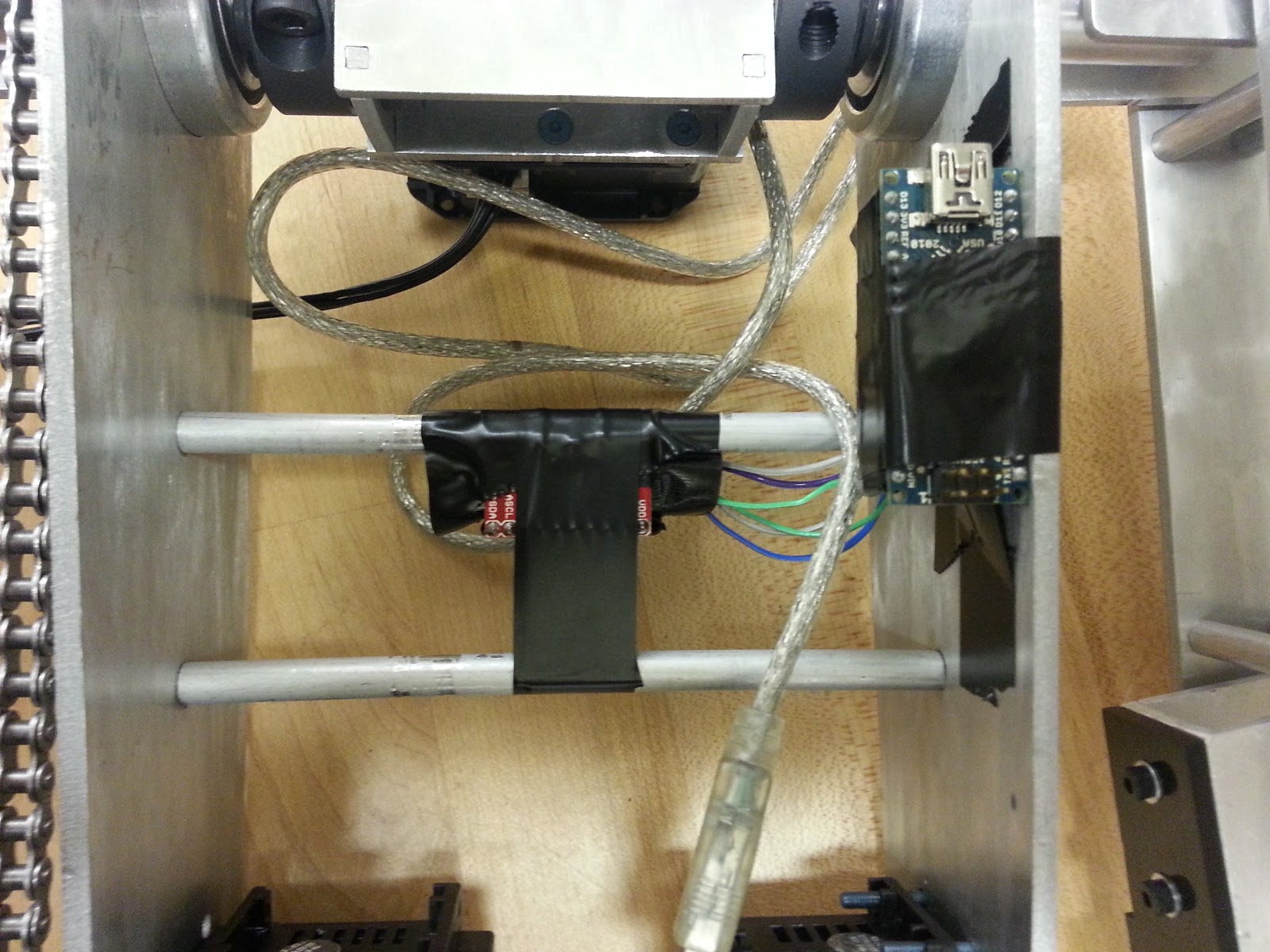
Next, I decided to start getting my board talking. After another few minutes screwing around with USB (At some point this semester I once managed to get the board to show up as a USB device on my computer... once. ) I decided to switch to Serial. I looked into using serial USART communication, and found out the two pins I routed for D+ and D- in USB are the same as RX and TX for one of the serial ports built into the atxmega16a4u chip on TinyArmTroller.
So I cut a USB 2.0-B cable and made an adapter for a Sparkfun FTDI Basic Breakout Board I had lying around. Good thing my dad had soldering equipment at home!
With this setup, and with the help of some example code I found online (which actually exists, UNLIKE F***ING USB) I was able to get it listening and talking! A few more hours of coding and I could send it six step (FROM MY COMPUTER!!) values as a waypoint (OVER SOME WIRES! :D).
I then took some time to re-calculate my estimated mapping of Angle to Steps, by moving each DOF to ~0 degrees, then to ~90 degrees, and seeing what step values took me there. Turns out, these numbers were very clean ones. For example, for the shoulder joint, -500 steps was 90 degrees, and -1400 steps was 0 degrees, leading the angle-to-step conversion to be :
(theta-140)*10 = #steps
The other DOFs followed similar patterns, and soon enough I was typing in a set of angles into the Python command line, and the arm was complying to my will! MUHUHAHAH! :D
Vid again:
Now, what does the future hold for my wonderful TinyArm? I need to solve the inverse kinematics, meaning I need to solve for some functions that will tell me "what angles do I need to command in order to get to a certain X,Y,Z,theta?". With that, I can place some blocks in stacks in front of it and have it rearrange them, or something. I can make it grab a pencil and start moving along the ground plane, tracking my mouse movements. When I click, the robot moves the pencil down, and I can write things with the arm. I can attach it to TurtleBot and use it as a manipulator arm to go get me sodas or something, because it could pick up upwards of 2 lbs. (4 lbs according to the Microbot website...) I can attach it to the underside of a quadrotor...
Allow me to describe some of the better parts of 2.12 (Introduction to Robotics) and its lab aspect before I start ranting about
WHAT A SHITSHOW THIS FINAL PROJECT WAS.
Ooh, Dynamic Motion Systems!
2.12 is an MIT class called Introduction to Robotics. Unlike 6.141, this class is administered by the Mechanical Engineering department, and the material it covers is way different.
6.141 focuses on modern techniques for mobile robotics such as Configuration Spaces, Accurate odometry, Computer Vision, Motion Planning, and SLAM and only dabbles with armature control and grasping. After taking 6.141 you will be comfortable moving a mobile robot around, accurately keeping track of its position in space, and planning valid paths based on visual and other feedback.
2.12, on the other hand, focuses on the design, motion, dynamics, and control of armature and dynamic robots. After taking 2.12, you will be able to design a robot that can bear a required load (Unlike the laughably weak 6.141 robot arms) and move robustly in the desired workspace, while controlling it with systems that can keep track of the dynamics and compensate for gravitational and other adverse effects on motion tracking. While the first few labs involve accurately moving a mobile robot platform using odometry from encoders, the main focus of the class is robust serial-link manipulators and highly dynamic systems.
After the first few frustratingly boring labs involving using LabView (Ugh. I should have been a CS major...) to control a mobile robot whose motor deadband is larger than the freaking moon, we finally got to the good stuff: dynamic control of underactuated systems! Here you see my buddies and teammates Tyler and Adrian watching a high bar gymnastic robot we just designed an energy-based controller for. This was the last follow-the-directions lab before the final project was announced.
The final project for 2.12 was to compete in the robolympics! Each lab section represented a "country", and each lab section competed in three different events. There was a High bar event (Whose team members had done the same dynamics preview lab as everyone... making their event seem trivial), a Floor event (where a robot had to do a dynamic roll on the ground), and a Rings event (basically a high-bar event, but with one added degree of complication).
The high-bar robot, and the robots we will be building, use these hard-to-use-with-Python (Remember that, it'll be important later.) but otherwise gorgeous Dynamixel servos. Peaking inside the airflow holes you can see a Maxon A-Max motor and a robust microcontroller inside. They can communicate over 4-wire Serial RS-232 or RS-484 or 3-wire TTL, and are individually addressable on the same bus. At the end of the bus you can attach a USB2Dynamixel adapter, and send commands to/receive state feedback from each servo.
For ~$350.00 each, they better have good hardware and features.
Makes me wonder, how could I turn a crappy pwm input servo into something better? A Science project for another day...
The Lord of the Rings is his name, and waterjetted parts is his game!
After much debate and arguing (read "Design"), the five-person team I was in came up with this biomimetic waterjet-able design for the rings robot. (YAY WATERJET ABUSE :D) It has a few Fundamental Flaws in design I'll talk about later, but it pretty accurately replicates the possible moves a human rings gymnast could perform. It has three degrees of freedom: Its arms can abduct apart about its "shoulders", the shoulder axis can rotate relative to its torso, and its legs can move relative to its torso.
This is the shoulder axle assembly. Made up of a couple tubes and a "gearbox" which contains the actuator and transmission for the arm abduction. The tubes allow for the center actuator to transmit power to the outer arm links through timing belts which run along the inside of the tube. The tube can then be supported by bearings in the Torso and be driven by a chain on the sprocket.
Here are the hips of the robot. The left actuator drives a chain which moves the shoulder axle assembly, while the right actuator has a horn which is directly attached to the leg assembly. (Now shown in either of these pictures are the standoffs that hold the parallel plates together.)
Moar waterjet abuse. Because some people on the team had switched to Solidworks Student Edition 2012-13 (myself included) and some others had metric default units (FUUUUUUUU), OMAX Layout took some coercing and debugging to import the .dxf files in the correct scale.
Finally. Parts. Are we done with the robot yet? Can I test my software yet?? (Oh yeah, that was another thing. While the software was supposed to be written by two other teammates and myself, I ENDED UP DOING IT ALL BY MYSELF. WTF GUYS?! RANTRANTRANT)
In order to focus more on the software that no. one. was. doing. but. me. I decided to not work on assembling the thing. Issue is, everyone but poor Tyler decided to pretty much not work on assembly either. And thus comes out one huge lesson in team engineering I learned: DON'T LET TEAM MEMBERS GET ACCUSTOMED TO NOT DOING ANYTHING. It got to the point where team members would show up to a build session, would take on building a part, would half-ass it and build it incorrectly, then leave. IF I HAD A DOLLAR FOR EVERY TIME THAT HAPPENED THIS SEMESTER...
The gearbox assembly looks good! But does it work? Nope. For two reasons: -One, the set screws on the little gears like to slip. Even when Loctited like all hell and cranking the set screw down on a flattened bit of shaft, the gear would slip. -_- -Two, the axle coupled to the servo output is SCREWED INTO THE SERVO. As in, IT UNTHREADS ITSELF when driven backwards. WHO THE HELL DESIGNED THIS?! Don't look at me. I'm just the software guy/assembly monkey/waterjet bitch. I should have caught this way earlier during the design process, though, which I was kinda involved in. To the team's credit, the TAs did say the servo would lock onto a shaft that was beasted into its output shaft. UGHHHHHHH Know what's worse? The output axle of the servo that drives the chain IS FASTENED IN THE SAME WAY.
Sigh. Moving on in our tour of the robot, please look out the left side of the vehicle. Here you can see the other end of those timing belts, and how they travel inside the pipe which moves in a bearing. Clever, huh?
You know what's NOT clever? See the axle the pulley is attached to? See how there's nothing coupling it to the rest of the arm at the bottom? They're supposed to be coupled. Again, I say FOR CRYING OUT LOUD, WHO THE HELL FORGOT TO TAKE THIS INTO ACCOUNT WHILE I WAS AWAY BEING A CODE MONKEY?!?! WHAT. THE. ACTUAL FU-
Aaaand Here's the completed Lord of the Rings! It took many hours of me and Tyler and not much of anyone else to get this thing together. Can I start testing my software yet? PLEASE?!
Mounted onto the robot is a Sparkfun MPU6050 IMU (Inertial Measurement Unit) Breakout Board, which provides 16-bit precision out of both 3-axis Gyroscope (Angular Velocity) and Accelerometer (Translational Acceleration), with configurable maximum output values. It communicated using a serial bus protocol called i2c, where each slave component on the bus can be individually addressed by a master, in this case an Arduino Nano. The Nano then communicates with my computer running high-level code via Serial over USB. On the computer I am running the software for the robot, written in Python. I wrote a general-purpose PID control module, used by pretty much every other module. A Dynamic Energy Controller contained the model of the robot (including the links, their lengths, masses, moments of inertia, distances to centers of mass, and equations for potential and kinetic energy) and hybrid multi-variable control to reach a desired kinetic and potential energy. For example, if you commanded maximum kinetic energy, the robot would start to swing up. If you commanded zero kinetic energy and maximum potential energy, the robot would stand up straight and balance in an inverted position. If you commanded zero total energy, the robot would come down and damp all oscillations. It was beautiful :,) A sensor module dealt with getting raw feedback from the IMU and servos, and parsing them using a Sensor Fusion module, which implemented a second-order complementary filter to get accurate readings for the robot's angle with respect to the ground. This full state feedback would then be sent into the Dynamic Motion Controller at each iteration of the main loop so it could constantly compute energy based on its internal model and generate desired torques to reach the desired energy state. (I should write DynaMo for ROS... Or a computed torque feed-forward controller... Takes in a URDF and full-state feedback and a desired energy states. Oohhh...)
Here's the Sensor Fusion module in action! I am SO proud if this, in case you haven't noticed :3 Nothing is more entertaining than moving your robot around IRL and seeing its on-screen model accurately keeping up with it. Amazing. I want to Segway. I want to Quadrotor. I want to self-balance.
Less than 12 hours before the final competition, THE ROBOT WAS FINALLY HUNG ON THE RINGS. Sweet Robot Jesus.
Soon. First, the final competition! In the end, the robot ended up not working for the final competition. The Dynamixel servos really did not like speaking with my computer, or many others for that matter, including the lab workstation. At one point one of the servos appeared to had died. At another point all 3 servos appeared to had died. Then, a few hours later after impoundment, all 3 servos detected. Way too late to test my code further. Then, during our presentation in front of hundreds of fellow MIT students and several professors who have taught me in the past few years, the robot did nothing.
THE ROBOT DID NOTHING. IN FRONT OF A FULL LECTURE HALL.
The servos would not communicate with the computer for some reason. At runtime, the servos "Failed to receive start bits, error 2". Again and again we tried, to no avail.
So it goes.
I learned a ton in this class, though, and I think that, other than this mishap in the final project, I did great in it. I just had the final exam today, and studying for it helped me realize how much better a dynamics analyzer and controls engineer I've become. Thank you, 2.12.
But now that you and I are over, I got other classes to finish... And a Melonchopper to build. And a TinyArmTroller to update and a TurtleBot to play with.