LONG TIME NO POST!
Here are the steps I took to add the RI to my 2019 CX-5. The steps are non-exhaustive, but are meant to aid in the following procedure that's already documented on Youtube:
Okay, here goes! Take a deep breath and DO IT!


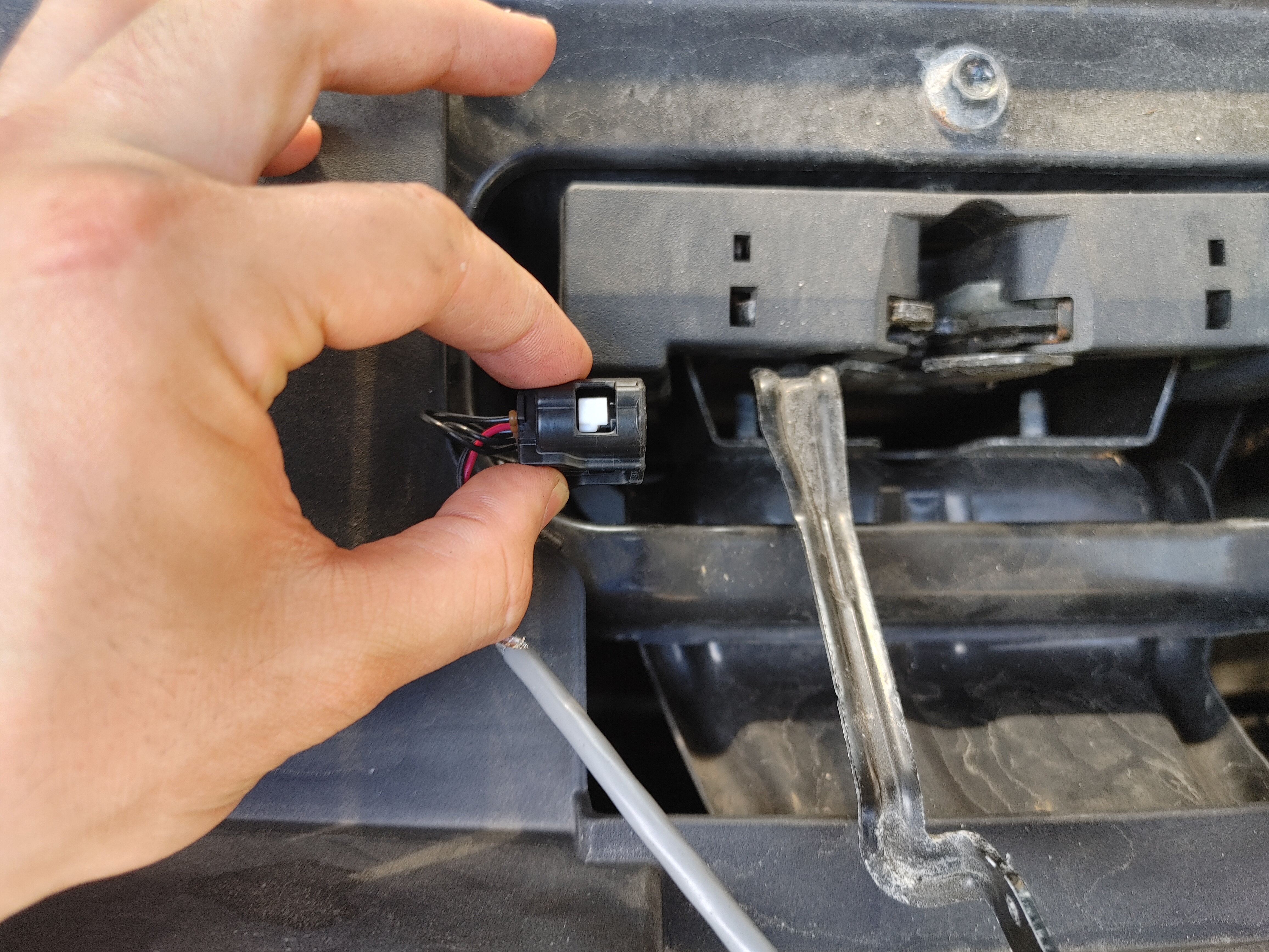
Here's the technique: reach your right arm in and turn your body to face the right side of the car. Your hand should easily reach the Radar connector. If you let go of it, that's ok! It dangles and is easily reachable.

Just grab it, hold down the connector tab HARD (which is facing the front of the car) and YANK! Use the same connector on the RI harness to practice the force needed to press down the tab.


To make the installation clean, pass the RI harness through the hood latch hole like this.


Note that I did not leave any of the cable coiled, and I passed it ALL through the firewall into the cabin. I added some zipties to hold the cable to the chassis bits under the rubber piece on the right. The cable was long enough to reach all the way up to my camera and Comma harness.

This is the big rubber piece that passes the wiring from the engine bay into the cabin, viewed from the engine bay. We're going to go around it. No need to remove the battery! You will be able to snake and reach the RI cables into the edge using the following technique

From under the steering column/dashboard, you can shove a screwdriver around the edge to make a little gap and a "hook" for the RI wires to hold onto. This image shoes the wires already in the cabin. I used pliers to pull them through once the first bits came through.

This is what it will look like from the engine bay. Remember to remove the screwdriver once all the slack is pulled through!
Now just remove the rubber skirt around the driver's side door (it just pulls off nondestructively), remove the bottom left panel, snake the cable through there, all the way up to the visor, across the front and into the injection molded camera case where the Comma harness is installed. I carefully removed the Orange CAN-H and Green CAN2-L pins from the white connector on the Comma harness, passed each wire through its own red splice connector, then reinserted the pins into the white connector. I then spliced in the red and black RI wires, using pliers to make sure the splice was secure (it's hard to do by hand).
