Allow me to describe some of the better parts of 2.12 (Introduction to Robotics) and its lab aspect before I start ranting about
WHAT A SHITSHOW THIS FINAL PROJECT WAS.
Ooh, Dynamic Motion Systems!
2.12 is an MIT class called Introduction to Robotics. Unlike 6.141, this class is administered by the Mechanical Engineering department, and the material it covers is way different.
6.141 focuses on modern techniques for mobile robotics such as Configuration Spaces, Accurate odometry, Computer Vision, Motion Planning, and SLAM and only dabbles with armature control and grasping. After taking 6.141 you will be comfortable moving a mobile robot around, accurately keeping track of its position in space, and planning valid paths based on visual and other feedback.
2.12, on the other hand, focuses on the design, motion, dynamics, and control of armature and dynamic robots. After taking 2.12, you will be able to design a robot that can bear a required load (Unlike the laughably weak 6.141 robot arms) and move robustly in the desired workspace, while controlling it with systems that can keep track of the dynamics and compensate for gravitational and other adverse effects on motion tracking. While the first few labs involve accurately moving a mobile robot platform using odometry from encoders, the main focus of the class is robust serial-link manipulators and highly dynamic systems.
After the first few frustratingly boring labs involving using LabView (Ugh. I should have been a CS major...) to control a mobile robot whose motor deadband is larger than the freaking moon, we finally got to the good stuff: dynamic control of underactuated systems! Here you see my buddies and teammates Tyler and Adrian watching a high bar gymnastic robot we just designed an energy-based controller for. This was the last follow-the-directions lab before the final project was announced.
The final project for 2.12 was to compete in the robolympics! Each lab section represented a "country", and each lab section competed in three different events. There was a High bar event (Whose team members had done the same dynamics preview lab as everyone... making their event seem trivial), a Floor event (where a robot had to do a dynamic roll on the ground), and a Rings event (basically a high-bar event, but with one added degree of complication).
The high-bar robot, and the robots we will be building, use these hard-to-use-with-Python (Remember that, it'll be important later.) but otherwise gorgeous Dynamixel servos. Peaking inside the airflow holes you can see a Maxon A-Max motor and a robust microcontroller inside. They can communicate over 4-wire Serial RS-232 or RS-484 or 3-wire TTL, and are individually addressable on the same bus. At the end of the bus you can attach a USB2Dynamixel adapter, and send commands to/receive state feedback from each servo.
For ~$350.00 each, they better have good hardware and features.
Makes me wonder, how could I turn a crappy pwm input servo into something better? A Science project for another day...
The Lord of the Rings is his name, and waterjetted parts is his game!
After much debate and arguing (read "Design"), the five-person team I was in came up with this biomimetic waterjet-able design for the rings robot. (YAY WATERJET ABUSE :D) It has a few Fundamental Flaws in design I'll talk about later, but it pretty accurately replicates the possible moves a human rings gymnast could perform. It has three degrees of freedom: Its arms can abduct apart about its "shoulders", the shoulder axis can rotate relative to its torso, and its legs can move relative to its torso.
This is the shoulder axle assembly. Made up of a couple tubes and a "gearbox" which contains the actuator and transmission for the arm abduction. The tubes allow for the center actuator to transmit power to the outer arm links through timing belts which run along the inside of the tube. The tube can then be supported by bearings in the Torso and be driven by a chain on the sprocket.
Here are the hips of the robot. The left actuator drives a chain which moves the shoulder axle assembly, while the right actuator has a horn which is directly attached to the leg assembly. (Now shown in either of these pictures are the standoffs that hold the parallel plates together.)
Moar waterjet abuse. Because some people on the team had switched to Solidworks Student Edition 2012-13 (myself included) and some others had metric default units (FUUUUUUUU), OMAX Layout took some coercing and debugging to import the .dxf files in the correct scale.
Finally. Parts. Are we done with the robot yet? Can I test my software yet?? (Oh yeah, that was another thing. While the software was supposed to be written by two other teammates and myself, I ENDED UP DOING IT ALL BY MYSELF. WTF GUYS?! RANTRANTRANT)
In order to focus more on the software that no. one. was. doing. but. me. I decided to not work on assembling the thing. Issue is, everyone but poor Tyler decided to pretty much not work on assembly either. And thus comes out one huge lesson in team engineering I learned: DON'T LET TEAM MEMBERS GET ACCUSTOMED TO NOT DOING ANYTHING. It got to the point where team members would show up to a build session, would take on building a part, would half-ass it and build it incorrectly, then leave. IF I HAD A DOLLAR FOR EVERY TIME THAT HAPPENED THIS SEMESTER...
The gearbox assembly looks good! But does it work? Nope. For two reasons: -One, the set screws on the little gears like to slip. Even when Loctited like all hell and cranking the set screw down on a flattened bit of shaft, the gear would slip. -_- -Two, the axle coupled to the servo output is SCREWED INTO THE SERVO. As in, IT UNTHREADS ITSELF when driven backwards. WHO THE HELL DESIGNED THIS?! Don't look at me. I'm just the software guy/assembly monkey/waterjet bitch. I should have caught this way earlier during the design process, though, which I was kinda involved in. To the team's credit, the TAs did say the servo would lock onto a shaft that was beasted into its output shaft. UGHHHHHHH Know what's worse? The output axle of the servo that drives the chain IS FASTENED IN THE SAME WAY.
Sigh. Moving on in our tour of the robot, please look out the left side of the vehicle. Here you can see the other end of those timing belts, and how they travel inside the pipe which moves in a bearing. Clever, huh?
You know what's NOT clever? See the axle the pulley is attached to? See how there's nothing coupling it to the rest of the arm at the bottom? They're supposed to be coupled. Again, I say FOR CRYING OUT LOUD, WHO THE HELL FORGOT TO TAKE THIS INTO ACCOUNT WHILE I WAS AWAY BEING A CODE MONKEY?!?! WHAT. THE. ACTUAL FU-
Aaaand Here's the completed Lord of the Rings! It took many hours of me and Tyler and not much of anyone else to get this thing together. Can I start testing my software yet? PLEASE?!
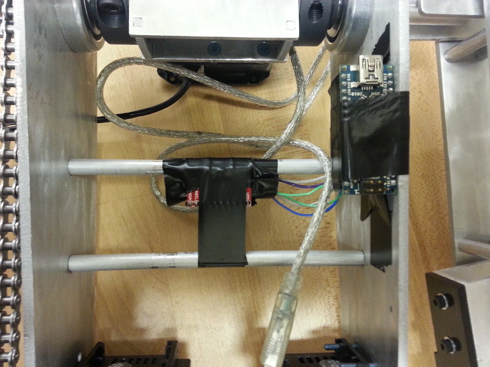
Mounted onto the robot is a Sparkfun MPU6050 IMU (Inertial Measurement Unit) Breakout Board, which provides 16-bit precision out of both 3-axis Gyroscope (Angular Velocity) and Accelerometer (Translational Acceleration), with configurable maximum output values. It communicated using a serial bus protocol called i2c, where each slave component on the bus can be individually addressed by a master, in this case an Arduino Nano. The Nano then communicates with my computer running high-level code via Serial over USB. On the computer I am running the software for the robot, written in Python. I wrote a general-purpose PID control module, used by pretty much every other module. A Dynamic Energy Controller contained the model of the robot (including the links, their lengths, masses, moments of inertia, distances to centers of mass, and equations for potential and kinetic energy) and hybrid multi-variable control to reach a desired kinetic and potential energy. For example, if you commanded maximum kinetic energy, the robot would start to swing up. If you commanded zero kinetic energy and maximum potential energy, the robot would stand up straight and balance in an inverted position. If you commanded zero total energy, the robot would come down and damp all oscillations. It was beautiful :,) A sensor module dealt with getting raw feedback from the IMU and servos, and parsing them using a Sensor Fusion module, which implemented a second-order complementary filter to get accurate readings for the robot's angle with respect to the ground. This full state feedback would then be sent into the Dynamic Motion Controller at each iteration of the main loop so it could constantly compute energy based on its internal model and generate desired torques to reach the desired energy state. (I should write DynaMo for ROS... Or a computed torque feed-forward controller... Takes in a URDF and full-state feedback and a desired energy states. Oohhh...)
Here's the Sensor Fusion module in action! I am SO proud if this, in case you haven't noticed :3 Nothing is more entertaining than moving your robot around IRL and seeing its on-screen model accurately keeping up with it. Amazing. I want to Segway. I want to Quadrotor. I want to self-balance.
Less than 12 hours before the final competition, THE ROBOT WAS FINALLY HUNG ON THE RINGS. Sweet Robot Jesus.
Soon. First, the final competition! In the end, the robot ended up not working for the final competition. The Dynamixel servos really did not like speaking with my computer, or many others for that matter, including the lab workstation. At one point one of the servos appeared to had died. At another point all 3 servos appeared to had died. Then, a few hours later after impoundment, all 3 servos detected. Way too late to test my code further. Then, during our presentation in front of hundreds of fellow MIT students and several professors who have taught me in the past few years, the robot did nothing.
THE ROBOT DID NOTHING. IN FRONT OF A FULL LECTURE HALL.
The servos would not communicate with the computer for some reason. At runtime, the servos "Failed to receive start bits, error 2". Again and again we tried, to no avail.
So it goes.
I learned a ton in this class, though, and I think that, other than this mishap in the final project, I did great in it. I just had the final exam today, and studying for it helped me realize how much better a dynamics analyzer and controls engineer I've become. Thank you, 2.12.
But now that you and I are over, I got other classes to finish... And a Melonchopper to build. And a TinyArmTroller to update and a TurtleBot to play with.
This video is from 2.12 (Intro to Robotics), a class I'm taking this semester. I got a Sparkfun MPU6050 Breakout Board to talk to an Arduino Nano via i2c, which then communicates with my Ubuntu laptop via Serial. A Python program interprets the Arduino serial signal as outputs of the sensor's Accelerometer[meters/(second^2)] and Gyroscope[degrees/second]. A second order complementary filter (More info on these style filters in Shane Colton's Blog) then interprets these signals as pitch, roll, and yaw angles. Which you can see on my computer screen represented as a line.
Updates on Melonchopper's build and more details on 2.12 coming soon!
This term I took 6.141 (Robotics: Science and Systems I), a class about life, love, and the pursuit of autonomous mobile robotics. Teams consisting of four students, usually from different majors, collaborate on the class’s seven labs as well as a 3-week Final Challenge, to implement a motley array of software-based techniques for robot navigation, localization, mapping, and manipulation. As an Institute Communication Intensive Laboratory class, we had several design proposals to do, both individual and team-based. Additionally, we had to give a presentation after each lab and a design overview before beginning work on the Final Challenge.
The Final Challenge had the following premise: An autonomous rover lands on Mars with the intention of building a predetermined structure for future human colonists to use.
Within the scope of the class, however, our robot simply had to navigate this maze, collect those blocks, and build some kind of structure in any way possible. Easy enough, right? We'll just make this thing:
The only exception (to my dismay) was no flamethrowers, saws, hammers, or other devices that can destroy or otherwise disassemble the environment may be used. Oh well...
The freedom for the robot's design allowed for each team to come up with a unique approach to solving the problem. Historically, most teams opted to use as much of the code from previous labs as possible, which involved active manipulation for collecting blocks, and a passive construction method of funneling the blocks into a structure on board the robot that could be placed in the environment.
My team, Team VI: The Sentinels, opted to go for the inverse, which was passive collection and active construction. We went for an (almost) entirely open-loop approach, using only the provided map and block locations, with killer wheel encoder odometry, for navigation.
See, our robot has no vision, bump, or distance sensing. Before we first demonstrated successful navigation, members of other teams started talking smack about our Sentinel, calling the poor thing "blind".
And it's certainly blind. Not one camera or sensor on that thing. We implemented Computer Vision with both a webcam and a Kinect, but in the end it wasn't really necessary because of our dead-accurate encoder odometry.
(We experimented with mounting two optical mice underneath the robot and using their readings as odometry. We conducted a test to see which was more accurate, the mice or the wheel encoders. Our robot started at one corner of a 1-meter square, and we gave it 10 waypoints, each at a random corner of that square. After multiple tests, we saw, to our surprise, that the wheel encoders consistently got it to within 2 centimeters of its final waypoint, while the optical mice always left it greater than 5 centimeters from that final waypoint. Clearly, we had some kick-ass encoders.)
Our robot robot navigated the maze, driving over blocks which would be collected by a bent sheet aluminum funnel suspended underneath.
As the blocks were collected, they slid along the funnel and into the space underneath that was sized such that the blocks would interlock and form a straight line.
Once we collected enough blocks, the robot drove to a spacious area of the maze and drove backwards to deposit the blocks in front of it.
And then construction began using only the provided manipulator which was actuated by hobby servos which were too weak for the job, prone to overheating, and proved to be nonlinear as a result. But it worked well enough:
We somehow got it working. First with my spearheading a teammate's bet that I couldn't get it to stack a 5 block tower. (If I got it working, I'd get $100.00. If I didn't, I got him a sandwich. A reasonable bet.) I got it working once, but with inconsistent results, winning the bet.
Then with hours of fine-tuning that sounded a lot like the above video does at 03:15
More fine tuning led to consistent behavior, 5 minutes of fame on the MIT EECS facebook and the 6.141 website (and an A). Above is footage of it stacking a tower. (Including Neil waking up in disbelief after sleeping on the ground for a couple hours. The life of an MIT student sure is a glamorous one.)
And footage of it completing an entire Challenge run. Complete with Will talking about my old dormitory, known in the 80s as "McKegger", and myself rambling on about all the nerdy stuff I learned (and didn't) in the class.
The other teams had some noteworthy designs as well, a class favorite being this bad boy.
This robot, like most 6.141 bots of the past, actively collected blocks using the manipulator and dumped them into a container in the back where they were passively assembled into a structure. The real innovation made by this team was the design of the back-mounted hopper, and the type of structure it left in its wake.
The initial blocks fall into place on the bottom, oriented 45 degrees up from the ground and aligned side-by-side. The following blocks fill in the gaps in between, stabilizing the structure, which is only supported by the corners of the bottom blocks.
When time is up, the hopper rotates back like a dump truck until the blocks contact with the ground. The robot then pulls away, leaving this arch-like structure.
The class was a blast and I learned a ton. Unfortunately, we don't get to keep the robots because they get disassembled for next year.