31 October 2012

The Spoils of Swapfest: MOTORS!

(Sounds like a book title, or something.)
MOTORS!
ALL THE MOTORS!


I found these gems from a couple of vendors at Swapfest. THREE MAXON MOTORS! THE BIG PITTMAN ONES HAVE 100 CPR QUADRATURE ENCODERS IN THEM!! I HAVE SEVEN OF THEM!!! *NERDGASMMMMMM!!!!!!*


SWAPFEST!

Swapfest is a monthly flea market hosted at MIT, where ass-tons of electronics and other hardware is sold from sketchy surplus purchasers. 
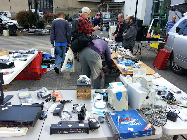


Look at all them electronics. 


Back to why I am so excited: 

Pittman/AMETEK... This is the same company that makes the two $200.00 gearmotors that I used in 6.141 last Spring. The same motor whose amazing quadrature encoders gave us insanely precise odometry. I basically own seven of the 6.141 motors, minus the heavy gearing (which I can easily do myself).


Here you can see the Quadrature Encoder connector, with the dark green shield cable
Some of you may be asking, what the is a quadrature encoder, anyway? Well a regular encoder is a system you attach to a shaft to measure rotation. Inside there's a small disk with holes cut out of it that looks like this: 

A light source and sensor pair are placed at the same radius away from the center shaft as the track, on opposite sides of this disk. As the beam is broken by the wheel, an interrupt is sent to whatever microcontroller is processing the encoder data and a counts value is iterated. 

But Dan, how do I know if it's spinning one way or the other? If I move the shaft back and forth, the micro will just keep adding values!

That's why the word Quadrature is so special. Quadrature encoder wheels look like this: 


They have two tracks on the disk, and have two light sensors instead of one.

First of all, this quadruples your resolution (hence the name "quadrature"). The tracks are 90-degrees out of phase, so every four ticks the pattern of Channel A to Channel B repeats: Black Black, Black White, White White, White Black. If you parse this correctly, you can determine which direction you're spinning. YAY!

With a strong build and an insanely high quadrature encoder resolution of 1000 counts per revolution The possibility of these motors are endless. I can put two of these on a mobile robot more powerful than TurtleBot's iCreate (In fact, I should start working on an Open-Hardware iRobot Create replacement Turtlebot-Compatible mobile platform!). I can use a few of these to make a low-DOF high-power manipulator. I can use all seven of them to make a high-quality 7-DOF manipulator comparable to the Barrett WAM arm
Woah...

So what exactly can these motors do?

Here's a laser Tachometer that measures how often a reflective tape passes its lens in RPM. I placed some aluminum tape over one side of a motor's output shaft. 


I hooked up a motor to a variable power supply and pointed the Tachometer to it, and did some Science. 


I took down my measured RPM at a range of voltages for the motor. The slope of the best fit line created by plotting these points will be the motor constant in RPM/Volt, seen here in cell A12. 
The data also makes for a pretty graph. Look at how linear DC motors are!

By taking the inverse of Kv, you can find Kt. This led me to the following  empirically-tested parameters:


Kv = 340.327 RPM/Volt = 35.639 radians per second per volt
Kt = 0.1763 newton meters per ampere

In order to get a VERY rough estimate of the max torque output of this thing, I held onto the motor shaft and applied some voltage until I couldn't hold it by hand anymore without hurting myself. I applied around 12V (which is good, I would probably use this off of an ATX power supply in the future) and read the current output as I stalled the shaft. The current went up to approximately 3 Amps. 
Kt * maxCurrent = .1763 Nm/A * 3 A = 0.5289 Nm at 12V


For teh lulz, I wanted to see if it could pick up a soda can. 

Soda can mass: .390kg =~ 1lb

Soda can gravitational force: .390kg*9.8m/s^2

.5289Nm/(.390kg*9.8m/s^2) = 5.45 Inches

This thing can cantilever a 1-lb load at almost 6 inches by my sketchy calculations. NICE!

Still curious to see what these motors could REALLY do, I decided to call up Pittman/Ametek to see if the datasheet was available on their end. Joe from their engineering tech support dept. was able to pull it up in seconds and email me the file, which contained a scan of an old-looking printout with some handwriting on it. The sheet is dated 1992, way back before human beings were civilized and purchased things on the internet.

Turns out their motor constant was ~ 332RPM/volt, so I'm pretty damn close. Their rated stall current is 10 Amps, so my 3-Amp estimate is way underrating the kind of power this thing could put out at 19.1 Volts! These are some kick-ass motors! 

AND I HAVE SEVEN OF THEM!


What's better than Pittman motors? Maxon Motors. Maxon is a Swiss company that makes beautiful motors for precision control, usually with planetary gearing and encoders built in. I first ran into them my first summer at MIT, working the for Media Lab Personal Robotics Group as a solder/code monkey on the team that made this adorable and cuddly robot. 

They're also hella expensive. A brushed Maxon gearmotor on their catalog today of this size (16mm diameter) will run you like $70.00. I got these for $5.00 each!

I'm too lazy to do the Tachometer thing with these motors, so I'll probably call up Maxon and try to get the datasheet somehow, because Maxon is notorious for taking their older model motors' datasheets offline. 

Halloween! AS TONY STARK

TONY STARK!

I will be Tony Stark for Halloween. Should I be in a sleeveless tee? How will I get my goatee as awesome as his? Should I wear a classy-ass suit? Regardless of the above design decisions (lol), I need an Arc Reactor. An hour of CAD and reading this Instructable, I was ready to lasercut using my I-Have-Friends-With-Lasercutter-Access skills. 


Laserlaserlaser
I lasercut the things!
 Assembly involved placing my white LEDs (that I purchased for dirt cheap off Amazon) and using this incredible precision time-based heat-controlled adhesive called Hot Glue. 


When in doubt, HOT GLUE
Yay! 
 3 volts makes it shiny. 6 volts makes them twice as shiny, so I decided to stack two 3-volt coin-sized cells.


YAYY!
 I now wanted to put something else Tony Stark-y on me before I attended Halloweekend festivities. Being an MIT alumnus, Tony Stark probably has his fair share of graphic tee shirts. He also owns Stark Industries, so he probably owns a Stark Industries graphic tee! I had a sleeveless shirt with me, which everyone can attribute to Tony Stark working at MITERS in his basement shop. and knowledge of custom PCB fabrication so...


Iron, man. 
The result was me printing out the Stark Industries logo backwards and attempting a toner transfer. 


Iron Man!
Success!-ish. I peeled off the paper and this is what was left, which is totally legit for dressing up as "I've-Been-In-A-Cave-For-A-Few-Months" Tony Stark For better results I would have left the heat on for much longer, and I would have used water to dissolve the paper rather than peeling it (and the toner) off the shirt. Thing is, that would've taken time to let dry. 


SO MANY LEDS! :D
My girlfriend decided to dress up as the TARDIS for Halloween, so she made herself a (flipping awesome) dress! I helped her make her LED-lit hat, which is supposed to be the light at the top of the TARDIS. We attempted to replicate this TARDIS hat we found on a blog, but due to time constraints, we ended up making something a little simpler. 


"Is that a Leatherman Wave in your pocket, or.. Oh, it is! Okay then..."
break;

21 October 2012

Introducing TurtleBot: My First (legit) Mobile Robot!

A WILD TURTLEBOT APPEARS! 

0_0!


POKEBALL, GO!


You caught a wild TurtleBot! Would you like to give your TurtleBot a nickname?
....no. 

TurtleBot has been added to the list of things I should blog about!


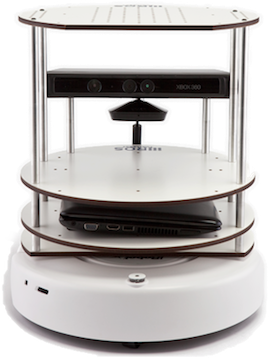
The Willow Garage Turtlebot is an open-hardware, low-cost, mobile personal robot platform that runs on open-source software. It consists of an iRobot Create, Aluminum standoffs and lasercut platforms, a Microsoft Kinect, a circuit board containing a Kinect power regulator and a single-axis gyroscope sensor, and an onboard laptop to interface with everything and bus data to a separate offboard workstation using Willow Garage's open-source Robot Operation System software (universally known as ROS).

Check out this overview of the TurtleBot, which just skims the surface of its potential:


Thanks to the ROS community's strong efforts to make difficult low-level problems such as motor control, computer vision, navigation, mapping, etc easily implementable, DIY roboticists, hackers, and even university researchers can very quickly develop high-level solutions to high-level problems like getting you a beer. The software base thus allows you to stand on their shoulders to achieve your goals. 

The release of the Microsoft Kinect, and the reverse-engineering of its protocol, marked a giant leap forward for DIY/low cost robotics everywhere. Now, a lab could own five Kinect-enabled robots for the price of one with a LIDAR. Anyone could just purchase themselves a Kinect and develop amazing software utilizing its 3D sensing. The TurtleBot is the manifestation of this Kinect revolution, offering a standard and robust platform for professional-quality Kinect-powered mobile robotics.


The iRobot Create base contains the wheels, drivetrain, drive electronics, battery, a wide variety of bump/distance/cliff/encoder sensors, and a parallel port for I/O, in a well-engineered $200.00 package. Essentially, a Roomba sans vacuum cleaner. 


Mounted on this base with aluminum standoffs are four platforms made of lasercut MDF for mounting or storing various "required" and additional hardware such as an onboard laptop, a Microsoft Kinect, or an optional robotic arm or something else on top. 

Or this Turtlebot's nifty beer tote I found on Google Images.
Like most projects I am going to spend a good chunk of money on, I spent days whether or not I should buy the thing. Then irresponsibly and in a sleep deprived state, I bought the $219.00 iCreate+Advanced Battery+Quick Charger package. Soon enough...


...I had it in hand! 
The product is very well constructed, from a design standpoint. Plenty of sturdy injection-molded parts held together with reputable hardware: I don't feel afraid to rough the 'bot around. In fact, when I ran the basic "Explore (vacuum) This Room" demo, it would drive right over cables and other objects (rather quickly, I might add), or just shove them aside altogether. Its large front-mounted dual-bump sensors hit obstacles quite forcefully, but the robot kept on going. 

There are three command buttons at the top of the robot, each with its own indicator light. For mounting hardware, iRobot put four 6-32 tapped holes on the top surface, allowing one to easily attach standoffs or screw peripherals to the Create. Taking a further look I found a DIN port for Serial/USB control (with the included cable adapter), a charge port, and the Cargo Bay Connector, which allows you to access various internal Create I/Os and drivers, Battery power and ground to convert as you please, regulated 5V power for peripherals, and other paraphernalia. 


When you pick up the robot while it's running, it stops its drive actuators and lets out a cute little "Uh Oh!" sound (^_^ SOO CUTE!!!). This is handy for when your robot is about to do something stupid like harass other MITERS denizens or unexpectedly drive out of MITERS and start exploring the hallway -_-. The killswitch occurs likely due to switches that exist on the wheel mounts, which open when the robot is lifted off the ground. Here you can see the spring-mounted caster and drive wheels (which I have yet to determine the power characteristics of). Not shown is another smaller caster wheel mounted opposite the front, which enables the Create to take on a larger load. When you set the Create down, its weight is enough to depress all three wheels. 

It's useful to note here that the iCreate has built in cliff sensors, which can sense the lack of floor right in front of it if it drives toward, say, stairs. Or the end of a table, like I had it run. I left the robot driving on an empty table for a few minutes, without robot-injury. I'm sure my poor robot didn't appreciate being so isolated, though :c. 

I'm not building an army, I swear...
Now that I actually had a $219.00 robot to care for in hand, it was time to give it some standoffs and platforms. I could have ordered the parts online pre-built. For $300.00 dollars. Hell, I could have ordered the entire pre-assembled Turtlebot, complete with iCreate, Kinect, Asus Laptop, aluminum standoffs, lasercut MDF, and Power/sensor board for $1,499.00 if I were some top-notch robotics research lab at a leading university with infinite dollars. 


Needless to say, I opted for the DIY approach. BECAUSE WTF 300 DOLLARS FOR FREAKING ALUMINUM STANDOFFS AND LASERCUT WOOD?!?  I enjoy the prospect of manufacturing what I can out of inexpensive/free raw materials. Luckily, the TurtleBot platform is open-hardware, and you can get more engineering drawings, circuit diagrams, design notes and CAD models than you can shake a KUKA manipulator at. I determined the size of each standoff and how I could make an equivalent one for cheaper. I also exported .DXF files of the platforms for future lasercutter use. 

I ordered a 6-foot long aluminum rod for $2.00 off Amazon, with free 2-day shipping. I also found a ton of .25" MDF lying around that a lab was getting rid of. I loaded up the .DXFs and fired up the lasercutter at CSAIL machine shop where my friend worked and the incredibly nice shopkeeper let me work. I had used the shop before to waterjet parts for Cruscooter and make the block funnel for my team's 6.141 robot


Rawr Lazar!

And I had the platforms within minutes! Now it was time to put them together with standoffs.


14 standoffs in total. and each of them needed tapped holes on each side for mounting. I grabbed my trusty Mountain Dew and got to work drilling them out...

One hole down, 27 to go! :D
After drilling them out, I spent hours straight hand-tapping holes at MITERS, and watched Rent and Iron Man in the process. I kept telling myself: You want to be doing this and only spend $2 on hardware. You want to be doing this and only spend $2... In order to interface the standoffs with each other, I sawed the caps off my surplus of 6-32 screws and threaded everything together.

Voila!
Now all I had to do was get a Kinect and a Power/Sensor board and I had myself a full Turtlebot! The issue with the powersensorboard is the recommended sensor breakout board is retired on Sparkfun, and the only package available for the actual gyro sensor IC is one which is impossible to solder traditionally. As a result, I could not etch my own board to spec as I planned, and had to purchase the premade $70.00-ish board. Oh well, at least I didn't have to debug it and drive myself insane like I usually do with my etched boards. 

I also purchased a Kinect for $50.00 on eBay  bringing the project's total cost to roughly $342.00. Not bad, considering a TurtleBot without the laptop from Clearpath Robotics will run you FREAKING $1,049.00. An uneducated consumer is their best customer. Or a filthy rich one. 

After mounting the Kinect and powersensorboard...

I HAVE A COMPLETED TURTLEBOT! YAY! :D


Now, it's time to code. Which is a lot harder than it sounds because it involves installing ROS and getting it working on both the host laptop and the robot. 

But I'll save that for later.