
Here's the final CAD! Here are the details of how I got to there!

I decided to use MDF because it's very quick to lasercut, inexpensive, light to be able to lug around to various shops on campus, and readily available in my lab. I enjoy and have a lot of experience making 3D structures out of 2D components and machining processes.

Here, I design the main clamping structural area to handle the clamping forces. I cut it up into 90-degree chunks and modeled each beam as a rectangular channel.

And this is the final side plate. There are four of these in total.

Here I begin dimensioning the linear slide axes for the components I can find readily online based on the calculations and decision I made in the last PUPS.

Here I consider the moment about the tool axis from tool crash forces. Because angular compliance isn't an issue here, (it is in fact desired to handle the possible +-5deg misalignment that may occur from the fastening operation), I designed these axes to handle the stress, but not be very stiff.

And here are the twin axes, shown with the front plate removed.


Showing off some linear motion in CAD.

It's important to note that both clamps and both axes all have the same linear guide rail and leadscrew architecture, for ease and homogeneity of design and components.


A cutaway of the vertical tool axis and of the leader clamp axis (The follower only has a pulley, no shaft coupling or servo). Note the twin bushings on the motor side, which are preloaded by a shaft collar and a conical spring. The other end of the shaft has a single bushing to handle radial loads, but allows for expansion and other linear motion of the leadscrew to prevent overconstraint. The distances between the components is tight, and the stacking of the 6 parts of the carriage presents a risk of overconstraint. To mitigate this, carriages were all assembled while on the guide rails, and the bolts that hold them together were the last to be tightened, ensuring a fit that is smooth and not interfering.


More details...

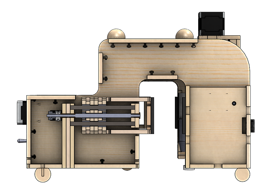
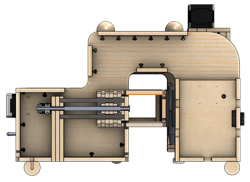
Showing off clamp range of motion from a side cutaway view...


And a top cutaway view.

The specific dimensions of the clamps were designed here to ensure stiffness under gravitational load.

These blue balls (heh) are used to couple 5 DOFs of the FASBot to the airframe. The 6th DOF is constrained by the pair of clamps.

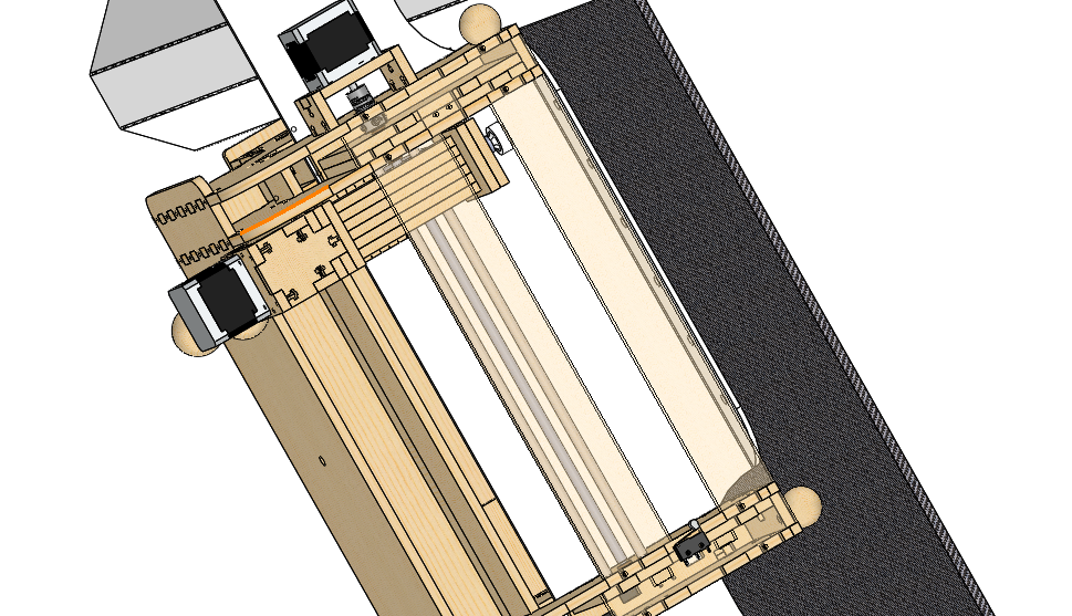
Here, the FASBot is shown in its natural environment... Note the three balls on the top of the FASBot. These will couple kinematically to the Parent Robot (not shown) using a magnet as preload. A hunk of steel will be bolted onto the hole that's in the center of stiffness of the three balls. The clamping force will be stronger than the magnet prleoad force, letting the Parent Robot to simply pull away from the FASBot once it's clamped to the wall. To pick it back up, it couples to the FASBot and the magnet engages with the steel to provide coupling preload. The FASBot then unclamps itself and is then attached to the Parent Robot, which can than remove it and place it at a new location inside the aircraft for further fastener installation.

Side view of the FASBot to Airframe coupling.

A closer look.
The FASBot-Airframe coupling procedure ideally places the nut driver tool right above the first fastener hole of the Shear Tie. The composite Shear Tie will have temporary tack fasteners at all sets of fasteners, and the adjacent set of fasteners will be installed, ensuring that the Shear Tie is held well against the Fuselage Skin despite the loading of the ~3-5lb FASBot.

As the tool goes down, it finds its target everytime. No need for heavy and expensive visual sensorheads!
Dear Sir / Madam
ReplyDeleteDo you need funds to start up your own business? Do you need loan to settle your debt or pay off your bills or start a nice business? Do you need funds to finance your project? We Offers guaranteed loan services of any amount and to any part of the world for (Individuals, Companies, Realtor and Corporate Bodies) interest rate of 2% within 1 year to 50 years repayment duration period to any part of the world. We give out loans within the range of $1,000 to $100,000,000 USD. Our loans are well insured for maximum security is our priority.
For application and more information send replies to the following
Lender's Name: Scott Tucker
Lender's Email: scotttuckerloanfund@gmail.com
What app Number: +16182279611
Attention Everybody, I am Colin Byrne by names, from United States. I want use this medium to say a special thanks to this awesome company who made it possible for me to improve my business. I was stuck in a financial crisis and i needed to refinance my business, i tried seeking loans from various loan firms both private and corporate but never with success and most banks declined my credit, until i met this company pennymac financial Services who helped me out with a loan sum of ($570,000) without any stress i truly want to thank Mr penny mac who made it possible and helped me through and ensure i got my loan. So i want use this means to advise everyone out there searching for a loan that if you must contact any firm with reference securing a loan with low interest rate and better repayment schedule to contact Mr pennymac at (pennymacfinancialservice0147@gmail.com). for a fast, safe and easy loan today...
ReplyDeleteGreat post! you deliver pupdate final design details in information in detail . I really like your post. Furthermore, This time to take advantages of garage door repair Acworth ga.
ReplyDeleteAppreciate your blogg post
ReplyDeletekuşadası transfer
ReplyDeletefoça transfer
alaçatı transfer
didim transfer
karşıyaka transfer
P5UF